
Hi All!
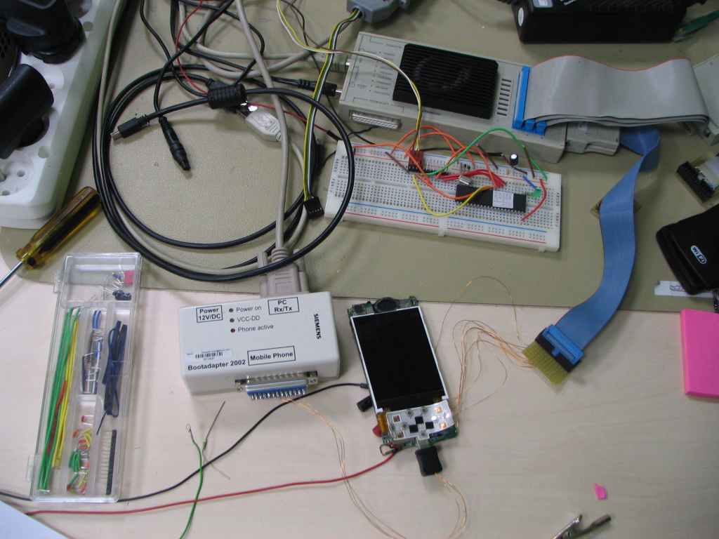
That's true, I managed to run U-Boot on MT6235, but linux kernel is not fully functional yet (it's fresh stuff as I managed to ran it on Tuesday and then I was off to conference). For MT6235 development I chose Sciphone G2, which is pretty cheap. After some time I managed to download code to SRAM (just 64KB) using MTK's FlashTool. MTK FlashTool communicates over UART directly with MT6235 bootloader and sends its own chunk of code (about 58KB) which is executed in SRAM and communicates with FlashTool. I found on pudn.com some pack to customize code loaded by FlashTool, thanks to which I could download my own code to SRAM (without JTAG). The problem was that it had to be linked with some security libraries which occupied about 56KB and not much memory left for my own code. Then I decided to try find JTAG pins to get all control on MT6235. That took me sometime, but finally I succeeded. The other bigger issue was initializing DRAM controller to be able to download bigger code (linux kernel + uboot) to external RAM. In sciphone there is problem that all interesting chips are under metal shield which is pretty havily soldered. In this case I couldn't read what kind of RAM memory is mounted without destroying the board (I don't have such soldering machine which could unsolder so big metal shield). Thanks to JTAG I could attach to target and then dump DRAM controller registers from processor running MTK's software, but setting these values after processor start and configuration of PLL didn't work. I decided to disassemble bootloader which could show me how DRAM controller is initialized and how code fron NAND is loaded (to be able to flash U-Boot and kernel to NAND so MT6235 will start my code automatically and I will not have to use JTAG). Currently I have knowledge how internal MT6235 bootloader is loading code from memory during startup and I also extracted procedure of DRAM controller initialization. Thanks to that I'm able to run U-Boot from the very begining of processor startup. The problem is that I have just one piece of Sciphone G2 and I don't want to flash it yet to not break existing code in it. Thanks to running device I'm able to attach with JTAG and check how peripherals are configured (i.e. LCD, MMC, etc.). I have backup of flash, but I'm not 100% sure if I will flash it back, phone will startup. That's why I bought second piece of Sciphone G2 and should receive it today or on Tuesday (this Monday is holiday in Poland). In this case I'll flash U-Boot to NAND and try to make it working. Then we could load the rest of code from U-Boot (to RAM or NAND over serial). You can see how my setup looks on attached picture. The good thing about it is that the same bootloader is used in MT622x, so it should be fairly easy to do the same on phones based on that SoCs (but unfortuantely it's just ARM7). If it comes to code, of course I can share it on "git.osmocom.org". Currently it's just basic port of U-Boot and not much for linux kernel, but I'm working on this now so I'll push it when it'll be ready.
Currently I'm working on driver for NAND memory for U-Boot, so we could flash linux kernel. When that will be ready I'll push the code. Then I'll switch to linux kernel and when it'll be functional I also push the code. At this stage you will not need to have JTAG and you could load the code over serial in U-Boot.
If it comes to GSM I didn't work with it before. I actualy worked 6 months in L2/3 team for LTE (on RRC) but it's different story. That could be really outstanding thing if we could run first phone ever with whole code open (from BB up to APP).
BR, Marcin

Hi Marcin,
thanks for introducing yourself and your project.
On Fri, Oct 29, 2010 at 08:14:50AM +0200, Marcin Mielczarczyk wrote:
That's true, I managed to run U-Boot on MT6235, but linux kernel is not fully functional yet (it's fresh stuff as I managed to ran it on Tuesday and then I was off to conference).
sure.
For MT6235 development I chose Sciphone G2, which is pretty cheap. After some time I managed to download code to SRAM (just 64KB) using MTK's FlashTool. MTK FlashTool communicates over UART directly with MT6235 bootloader and sends its own chunk of code (about 58KB) which is executed in SRAM and communicates with FlashTool.
Have you tried to use the MT622x support in osmocon ? Steve Margraf has added support for MT622x to it, you can see it from http://git.osmocom.org/gitweb?p=osmocom-bb.git;a=commitdiff;h=dd95bcec33237d...
If we assume the ROM loader of MTK has not changed between MT622x and MT623x, it may actually work.
I found on pudn.com some pack to customize code loaded by FlashTool, thanks to which I could download my own code to SRAM (without JTAG). The problem was that it had to be linked with some security libraries which occupied about 56KB and not much memory left for my own code.
Ok, I see. Could you provide that code? Do you know if the MTK secure boot mode is used on the phone model you use? If yes, than indeed it will need some cryptographic verified 2nd stage loader, Dieter has done some investigation on this.
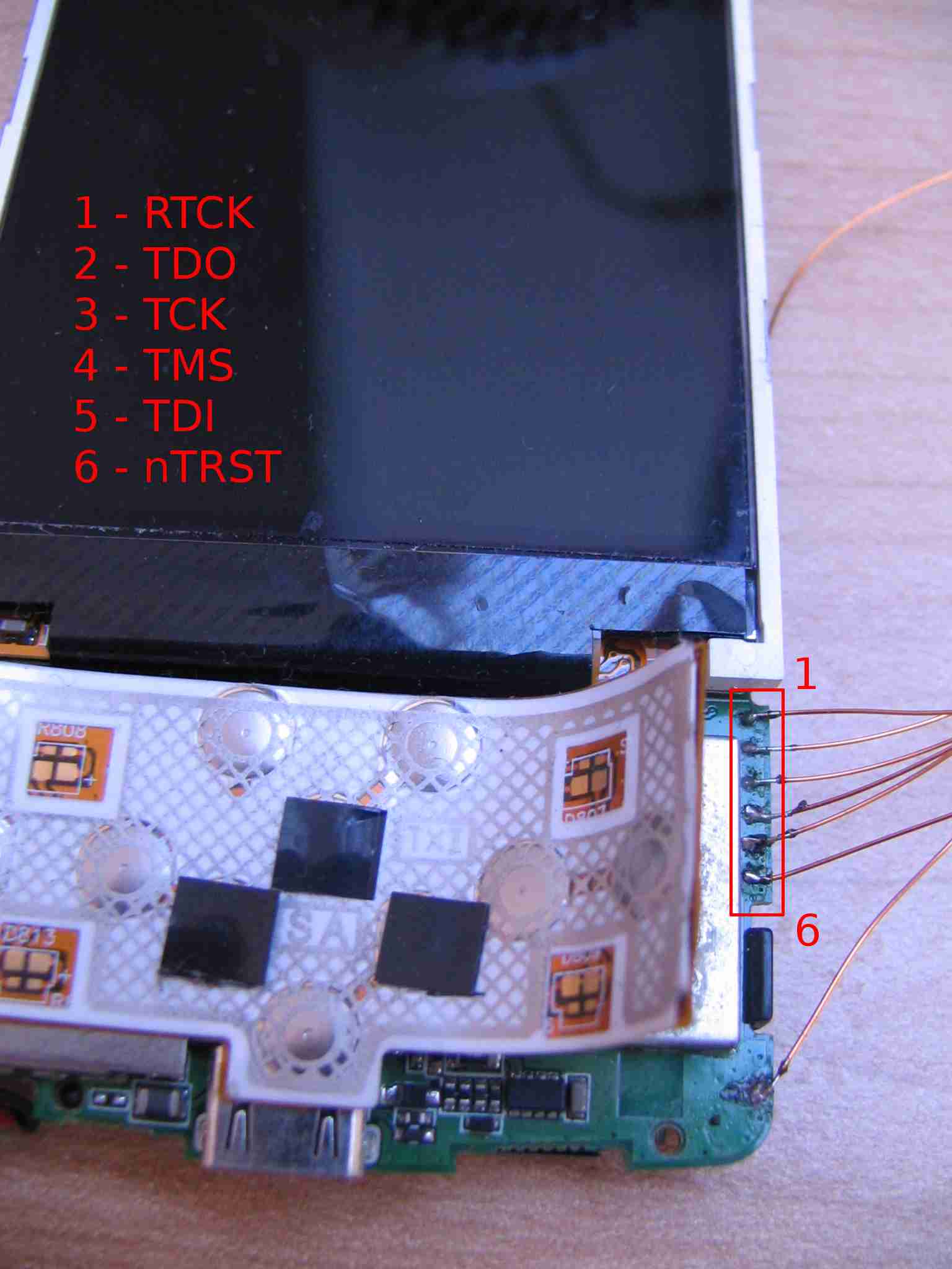
Then I decided to try find JTAG pins to get all control on MT6235. That took me sometime, but finally I succeeded.
This is great. So far, we have not seen any MT622x based phone that has JTAG exposed. Even the Huayu development modules for the MT622x don't have it.
The other bigger issue was initializing DRAM controller to be able to download bigger code (linux kernel + uboot) to external RAM. In sciphone there is problem that all interesting chips are under metal shield which is pretty havily soldered. In this case I couldn't read what kind of RAM memory is mounted without destroying the board (I don't have such soldering machine which could unsolder so big metal shield).
Using a scalpel to remove the shielding sometimes is easier than unsoldering. Other people have reported success using a small dremel tool.
Thanks to JTAG I could attach to target and then dump DRAM controller registers from processor running MTK's software, but setting these values after processor start and configuration of PLL didn't work.
Yes, typically for DRAM there is some kind of initialization sequence that you run through, it's not just a static set of registers.
I decided to disassemble bootloader which could show me how DRAM controller is initialized and how code fron NAND is loaded (to be able to flash U-Boot and kernel to NAND so MT6235 will start my code automatically and I will not have to use JTAG). Currently I have knowledge how internal MT6235 bootloader is loading code from memory during startup and I also extracted procedure of DRAM controller initialization. Thanks to that I'm able to run U-Boot from the very begining of processor startup.
this is great.
The problem is that I have just one piece of Sciphone G2 and I don't want to flash it yet to not break existing code in it.
Sure. Even today, we don't flash any of our OsmocomBB software to the target phone yet. Loading code in ram and executing it is much more convenient for development anyway.
I think if you can publish the pinout of the JTAG on the Sciphone G2, this would be sufficient for other people to join the project. Many people have a JTAGkey, Openmoko debug board or other OpenOCD compatible JTAG adapter...
The second step would be to go back to the ROM loader again and try to get code running through this again. In the end, we will need a development mode where we can e.g. load u-boot via the ROM loader (serial) and then load the kernel + rootfs from SD/MMC card. This should provide rapid development cycles.
You can see how my setup looks on attached picture.
Great :)
The good thing about it is that the same bootloader is used in MT622x, so it should be fairly easy to do the same on phones based on that SoCs (but unfortuantely it's just ARM7).
If it is the same, we should already have code for it (see above).
If it comes to code, of course I can share it on "git.osmocom.org". Currently it's just basic port of U-Boot and not much for linux kernel, but I'm working on this now so I'll push it when it'll be ready.
Please send your SSHv2 public key to me in private e-mail and I will give you an account on our git server for u-boot.
Currently I'm working on driver for NAND memory for U-Boot, so we could flash linux kernel. When that will be ready I'll push the code.
great. I think SD/MMC support is almost equally important.
It is definitely interesting for us to follow your work if you simply do your changes (even if it's not working yet, or unstable) in git.
If it comes to GSM I didn't work with it before.
That shouldn't matter - this is where our experience comes in. There are a lot of unknown variables when it comes to the MT6235 and the corresponding ABB and RF transceiver chips, but given that we've done similar work before for the Calypso, and that we now have a vision where we can run Linux with a L1 inside the kernel and L2/L3 in userspace programs, there should be quite some motivation to make it work.
Regards and thanks for all the good news, Harald
Hi,
On Fri, Oct 29, 2010 at 6:11 PM, Harald Welte laforge@gnumonks.org wrote:
Have you tried to use the MT622x support in osmocon ? Steve Margraf has added support for MT622x to it, you can see it from http://git.osmocom.org/gitweb?p=osmocom-bb.git;a=commitdiff;h=dd95bcec33237d...
If we assume the ROM loader of MTK has not changed between MT622x and MT623x, it may actually work.
No I didn't do this, but of course I can try it.
Ok, I see. Could you provide that code? Do you know if the MTK secure boot mode is used on the phone model you use? If yes, than indeed it will need some cryptographic verified 2nd stage loader, Dieter has done some investigation on this.
In this case, first I'll explain how it works. Nomenclature: 1) internal bootloader - bootloader placed at 0x48000000 in System ROM 2) 2nd stage bootloader or extarnal bootloader - bootloader placed in NAND - initializes DRAM controller and boots MTK's software - this bootloader prints info on UART by default
When MT6235 processor starts it has RM1 bit disabled in EMI_GENA register (External Memory Interface controller), which forces ARM926 core to jump first to System ROM (0x48000000). When internal bootloader is executed it initializes UART to 19200n8 and checks if specific character is received. If no character will be received it continues "normal" boot, so fetches code from NAND (checks bootloader header at 0x0 address, then gets 2nd stage bootloader from NAND). In this case there is no security at all. If we would like to boot from NAND, it's just matter of placing proper bootloader header at address 0x0 in NAND, and then placing U-Boot in proper addresses of NAND (I saw that internal bootloader doesn't fetch code from continues addresses, which means that code is scattered). The prove there is no security is that I can execute my own code from the very beginning. When I initialize CPU with JTAG it's hold at 0x0 address (first address executed) and then I just initialize PLL, DRAM controller, load UBoot to external RAM and execute it. Everything works perfect. There is Secure Engine (SEJ) in MT6235 to protcect program in external memory, but it doesn't look like it's used. The other story is second path which can be taken in internal bootloader. This path is taken when some character will be received by UART at the beginning of internal bootloader startup. That's where FlashTool comes in. Flashtool communicates with internal bootloader and sends its own chunk of code which is executed in SRAM. This code is called Download Agent (DA) and it's linked against some security libraries. If you'll try to download your own code (without these libraries) through FlashTool it'll just fail. You can find DA customization kit under following link: http://en.pudn.com/downloads153/sourcecode/comm/mtk/detail675309_en.html
This is source code where you can build your own Download Agent. This is how I first executed my own code on MT6235. It has all make files and it's prepared for ADS compiler. When you'll build your own Download Agent you just select this file in FlashTool and you have your code executed in RAM. I saw that you can use it on all MTK platforms. FlashTool links are also available on pudn.com I didn't analyze this path of bootloader, but it could be good to have it if we would like to create our own flashing tool under Linux (i.e. for flashing U-Boot).
This is great. So far, we have not seen any MT622x based phone that has JTAG exposed. Even the Huayu development modules for the MT622x don't have it.
It means that I was lucky ...
Using a scalpel to remove the shielding sometimes is easier than unsoldering. Other people have reported success using a small dremel tool.
Exactly, I wanted to do this with dremel tool but keyboard is sticked on that metal shield (it's visible on attached picture). If I would remove it, then it would be not possible to assemble my phone back. I had just one piece, so decided to make more elegant way.
Yes, typically for DRAM there is some kind of initialization sequence that you run through, it's not just a static set of registers.
In this case there is register EMI_CONN which has to have single bits enabled/disabled one by one for init sequence. That was the missing point.
Sure. Even today, we don't flash any of our OsmocomBB software to the target phone yet. Loading code in ram and executing it is much more convenient for development anyway.
I agree, but now I have bootloader disassembled and I think it could be possible to download UBoot permanently without risk. We could use that to load our own code to RAM over MMC/SD/serial.
I think if you can publish the pinout of the JTAG on the Sciphone G2, this would be sufficient for other people to join the project. Many people have a JTAGkey, Openmoko debug board or other OpenOCD compatible JTAG adapter...
Of course, no problem. In attachment you can find pinout of JTAG for Sciphone G2.
The second step would be to go back to the ROM loader again and try to get code running through this again. In the end, we will need a development mode where we can e.g. load u-boot via the ROM loader (serial) and then load the kernel + rootfs from SD/MMC card. This should provide rapid development cycles.
Yes, I agree. In this case to download U-Boot to NAND we can use FlashTool (only for Windows). Then as you stated we can use U-Boot to load code from SD/MMC/serial.
If it is the same, we should already have code for it (see above).
That's great!
It is definitely interesting for us to follow your work if you simply do your changes (even if it's not working yet, or unstable) in git.
OK, no problem.
That shouldn't matter - this is where our experience comes in. There are a lot of unknown variables when it comes to the MT6235 and the corresponding ABB and RF transceiver chips, but given that we've done similar work before for the Calypso, and that we now have a vision where we can run Linux with a L1 inside the kernel and L2/L3 in userspace programs, there should be quite some motivation to make it work.
That's great.
BR, Marcin

Hi Marcin,
On 30.10.2010 13:51, Marcin Mielczarczyk wrote:
In this case, first I'll explain how it works. Nomenclature:
- internal bootloader - bootloader placed at 0x48000000 in System ROM
- 2nd stage bootloader or extarnal bootloader - bootloader placed in
NAND - initializes DRAM controller and boots MTK's software - this bootloader prints info on UART by default
When MT6235 processor starts it has RM1 bit disabled in EMI_GENA register (External Memory Interface controller), which forces ARM926 core to jump first to System ROM (0x48000000). When internal bootloader is executed it initializes UART to 19200n8 and checks if specific character is received.
Alright, this is how it works on the MT622x as well.
This is source code where you can build your own Download Agent. This is how I first executed my own code on MT6235. It has all make files and it's prepared for ADS compiler. When you'll build your own Download Agent you just select this file in FlashTool and you have your code executed in RAM. I saw that you can use it on all MTK platforms. FlashTool links are also available on pudn.com I didn't analyze this path of bootloader, but it could be good to have it if we would like to create our own flashing tool under Linux (i.e. for flashing U-Boot).
That's pretty interesting, since it could be used to create authentificated code for other phones with the secure romloader, too.
This is great. So far, we have not seen any MT622x based phone that has JTAG exposed. Even the Huayu development modules for the MT622x don't have it.
Well, there is the CECT C3100 which has JTAG solder pads. OpenOCD successfully detected the CPU, but I couldn't halt the ARM core (same problem on the Calypso btw). I tried other random ARM7 targets which had the same EmbeddedICE revision and there it worked.
Yes, I agree. In this case to download U-Boot to NAND we can use FlashTool (only for Windows). Then as you stated we can use U-Boot to load code from SD/MMC/serial.
Getting osmocon to work with the secure romloader could be an option as well. Currently it only supports the non-secure romloader without that *.auth and SLA_Challenge.dll stuff. Plus we have a CFI-flash driver for the Compal phones, which might work on the MTK platform with a few modifications. If that works, we could flash U-Boot without any proprietary Flashtool/DownloadAgent.
Regards, Steve

Steve Markgraf wrote:
This is great. So far, we have not seen any MT622x based phone that has JTAG exposed.
Well, there is the CECT C3100 which has JTAG solder pads. OpenOCD successfully detected the CPU, but I couldn't halt the ARM core (same problem on the Calypso btw). I tried other random ARM7 targets which had the same EmbeddedICE revision and there it worked.
Did you check the config? I've seen bad reset signal settings in tcl/target/*.cfg (trst/srst) which stopped me from getting proper control over the core.
//Peter
Hi Steve
On Sat, Oct 30, 2010 at 2:53 PM, Steve Markgraf steve@steve-m.de wrote:
Alright, this is how it works on the MT622x as well.
I thought so, as I already saw that bootloader checks hardware ID and compares it with values 6228, 6226, 6223, etc.
That's pretty interesting, since it could be used to create authentificated code for other phones with the secure romloader, too.
That's true, it should work.
Well, there is the CECT C3100 which has JTAG solder pads. OpenOCD successfully detected the CPU, but I couldn't halt the ARM core (same problem on the Calypso btw). I tried other random ARM7 targets which had the same EmbeddedICE revision and there it worked.
I see that we were going through the same stuff. I had the same problem with Sciphone G2. I could attach to core but I couldn't halt it. At the beginning I detected just four JTAG lines (TCK, TMS, TDI, TDO) and could attach to CPU, but couldn't do more. Then I discovered two more lines: RTCK and nTRST. When I connected them, I still couldn't halt core, but it was just matter of configuration. When PLL is configured (CPU: 208/104MHz, AHBx4: 52MHz and AXBx8: 104MHz) 10MHz clock for JTAG should be used. When PLL is not configured, then RTCK clock should be used. I use Lauterbach for JTAG communication, but in openOCD should work as well.
Getting osmocon to work with the secure romloader could be an option as well. Currently it only supports the non-secure romloader without that *.auth and SLA_Challenge.dll stuff. Plus we have a CFI-flash driver for the Compal phones, which might work on the MTK platform with a few modifications. If that works, we could flash U-Boot without any proprietary Flashtool/DownloadAgent.
Sounds good.
BR, Marcin
Hi Marcin,
did you ever find schematics of the Sciphone G2 anywhere online? It would be great to understand which of the I/O lines are connected to which peripherals, especially for the GSM part.
Also, do you know the RF transceiver chip used in the device? We already know the MT6129 and MT6139 from the MT622x based phones, but it might be a different one for the MT6235.
Hi Harald,
On Sat, Oct 30, 2010 at 4:25 PM, Harald Welte laforge@gnumonks.org wrote:
Hi Marcin,
did you ever find schematics of the Sciphone G2 anywhere online? It would be great to understand which of the I/O lines are connected to which peripherals, especially for the GSM part.
No I haven't found schematics for Sciphone G2. That's the only thing missing actually. But I found MT6235 reference schematics and I don't think Sciphone change to much. Schematics are attached in this message.
Also, do you know the RF transceiver chip used in the device? We already know the MT6129 and MT6139 from the MT622x based phones, but it might be a different one for the MT6235.
It's under plastic antenna, but it seems that I can unsolder it so I can check. I checked on reference schematics and there is MT6140D.
BR, Marcin
Hi,
Also, do you know the RF transceiver chip used in the device? We already know the MT6129 and MT6139 from the MT622x based phones, but it might be a different one for the MT6235.
I unsoldered plastic antenna, but there is only WiFi. Seems that RF transceiver is under metal shield. I just received second piece of Sciphone and uploaded new pictures with descriptions on Wiki:
http://bb.osmocom.org/trac/wiki/SciphoneDreamG2
Good thing is that I can fit my microSD card sniffer which will make SD controller development easier. First I'll try to identify GPIOs.
BR, Marcin

Marcin,
I unsoldered plastic antenna, but there is only WiFi. Seems that RF transceiver is under metal shield. I just received second piece of Sciphone and uploaded new pictures with descriptions on Wiki:
I very much enjoyed reading your Sciphone G2 news and it motivated me to jump in and try to help :-) So it turns out a good friend of mine is Vice President of the company that made the Sciphone G2 - it's a small world after all. I wrote up what I found so far http://en.qi-hardware.com/wiki/Sciphone_Dream_G2
The G2 was discontinued about a year ago, but over 200,000 were made so we should be able to find some still. He donated the absolute last 2 phones we could find in his office to the OsmocomBB project, a normal black one as well as a prototype red one. He also donated another 9 boards to OsmocomBB, I took this picture http://en.qi-hardware.com/wiki/File:Nine_Sciphone_G2_boards.jpg
They are reworked/fixed, but _should_ work (note that 3 are without Wi-Fi). Now my question: For those 9 boards, what are the most important missing pieces so they can become useful for the OsmocomBB project?
I guess a charger/USB cable would be nice (it's not a standard plug). What else? LCM? Maybe not so important? How about antennas? speaker/buzzer?
If I just send these 9 boards to Harald the way they are on the picture, is that useful? Or should I try to find some more parts? I'm most concerned about the antenna, not sure whether this is easy to source/find.
Separately, I will try to take pictures of the individual PCB layers, using a V3.1 PCB. I should have them by the end of the week. I am also trying to get the schematics, maybe BOM or other helpful data, but I'm not so sure on those, maybe they cannot find them anymore even if they would like to give them to us. Don't hold your breadth on those.
Bottom line: 2 full G2 + 9 PCBA donated to OsmocomBB, PCBA pictures uploaded, PCB layer pictures coming. Schematics maybe.
Wolfgang
On Wed, Nov 3, 2010 at 6:41 PM, Wolfgang Spraul wolfgang@sharism.cc wrote:
Marcin,
I very much enjoyed reading your Sciphone G2 news and it motivated me to jump in and try to help :-) So it turns out a good friend of mine is Vice President of the company that made the Sciphone G2 - it's a small world after all. I wrote up what I found so far http://en.qi-hardware.com/wiki/Sciphone_Dream_G2
I'm realy suprised :) I didn't expect taht it'll go that far.
The G2 was discontinued about a year ago, but over 200,000 were made so we should be able to find some still. He donated the absolute last 2 phones we could find in his office to the OsmocomBB project, a normal black one as well as a prototype red one. He also donated another 9 boards to OsmocomBB, I took this picture http://en.qi-hardware.com/wiki/File:Nine_Sciphone_G2_boards.jpg
That's great news!
They are reworked/fixed, but _should_ work (note that 3 are without Wi-Fi). Now my question: For those 9 boards, what are the most important missing pieces so they can become useful for the OsmocomBB project?
I guess a charger/USB cable would be nice (it's not a standard plug). What else? LCM? Maybe not so important? How about antennas? speaker/buzzer?
For sure these 9 boards will be useful for this project. Besides running osmocomBB we have to run Linux with drivers for MTK peripherals: GPIO, SD/MMC, NAND, I2C, SPI, UART, PWM, USB, LCD, etc. Most of these peripherals are available on mentioned boards so they'll be useful for drivers development. If it comes to USB cable, it's not that important because L12C connectors (which are in Sciphone G2) are pretty cheap and available here:
http://www.ipmart.com/main/product/Cable,Compatible,for,China,Mobile,Phone,C...
So even without USB cables, LCD, antennas, speakers, etc. boards will be useful for some people.
If I just send these 9 boards to Harald the way they are on the picture, is that useful? Or should I try to find some more parts? I'm most concerned about the antenna, not sure whether this is easy to source/find.
I already answered above.
Separately, I will try to take pictures of the individual PCB layers, using a V3.1 PCB. I should have them by the end of the week. I am also trying to get the schematics, maybe BOM or other helpful data, but I'm not so sure on those, maybe they cannot find them anymore even if they would like to give them to us. Don't hold your breadth on those.
Wow, but I'm not holding my breath yet :) Schematics would be realy useful ... You can also ask about technical documentation for BT chip MT6601. I couldn't find datasheet and it'll be needed to make BT working.
Bottom line: 2 full G2 + 9 PCBA donated to OsmocomBB, PCBA pictures uploaded, PCB layer pictures coming. Schematics maybe.
That's very good news! I appreciate your help.
BR, Marcin

For sure these 9 boards will be useful for this project. Besides running osmocomBB we have to run Linux with drivers for MTK peripherals: GPIO, SD/MMC, NAND, I2C, SPI, UART, PWM, USB, LCD, etc.
Count me in for this work. I have to admit I never got around to test my Motorola-phones, but the vision to do a full Linux-port surely adds some endorphine here :)
Bottom line: 2 full G2 + 9 PCBA donated to OsmocomBB, PCBA pictures uploaded, PCB layer pictures coming. Schematics maybe.
BTW while looking for a source for the G2 in Europe, I found this:
http://www.digizo.co.uk/products/G2-Sci-phone-Google-Android-Interface-Dream...
Dunno if the price is good, but they seem to have a few in stock at least. (I was lucky though to find a used one in London during the two days I was there :))
Regards,
Wolfram
Hi,
On 03.11.2010 22:24, Wolfram Sang wrote:
BTW while looking for a source for the G2 in Europe, I found this:
http://www.digizo.co.uk/products/G2-Sci-phone-Google-Android-Interface-Dream...
I ordered there yesterday, and the phone shipped today.
Dunno if the price is good, but they seem to have a few in stock at least. (I was lucky though to find a used one in London during the two days I was there :))
The price is okay, a few other sellers from Hongkong charge ~90€ as well. The benefit of having it shipped from the UK is no hassle with customs, of course.
Regards, Steve
Marcin et al,
Wow, but I'm not holding my breath yet :) Schematics would be realy useful ... You can also ask about technical documentation for BT chip MT6601. I couldn't find datasheet and it'll be needed to make BT working.
sorry it took a bit longer than I thought, but I was hard at work and can report some good progress.
A package with 4 full G2 + 4 PCBA + some USB cables and batteries is on the way to Harald with EMS. Let's hope it arrives soon and without big customs problems. Thanks to generous Bluelans support, I have more stuff here, another 6 full phones (4 with buggy touch panel, 2 should be OK), plus another 4 or 5 PCB. I grinded down 2 PCBs to take pictures of the layers, and I broke another full set to make an illustrated disassembly guide. That set is probably still usable, although at least I ripped off the touch panel cable, and broke the glass under the touch panel, and maybe added some more damage as part of me making the disassembly guide. Well, hopefully it helps others making a safer disassembly, that was the point of it.
I kept adding things to my G2 wiki page http://en.qi-hardware.com/wiki/Sciphone_Dream_G2
What we have now is:
1) disassembly guide 2) PCB layers, also 1 large PDF with all layers so it should be easy to flip pages and follow traces 3) G2 schematics PDF, thanks to Bluelans 4) bottom side (LCM side) component placement, thanks to Bluelans
That pretty much concludes what I planned to do. Maybe they can find the top side component placement file as well, that would be nice. Not sure though. Also if the first package of phones arrives safely, I have more phones and boards I can send people. I plan to give away everything I have.
One thing you could help me with is URLs to the datasheets, as many as we can find, or have open URLs for. http://en.qi-hardware.com/wiki/Sciphone_Dream_G2#Key_Components
You mentioned you are looking for MT6601, I can start to ask around a bit, also for the full 6235 SDK if we can find it somewhere. But I don't even have links to the 6235 or 6140 datasheets right now...
Hope this helps, good luck for your work! Wolfgang
Hi Wolfgang,
On Tue, Nov 9, 2010 at 5:57 AM, Wolfgang Spraul wolfgang@sharism.cc wrote:
Marcin et al,
guide. Well, hopefully it helps others making a safer disassembly, that was the point of it. I kept adding things to my G2 wiki page http://en.qi-hardware.com/wiki/Sciphone_Dream_G2
Don't worry about broken touchpanel, this set will be still usable. Thank you for documenting it!
What we have now is:
- disassembly guide
- PCB layers, also 1 large PDF with all layers so it should be easy
to flip pages and follow traces 3) G2 schematics PDF, thanks to Bluelans 4) bottom side (LCM side) component placement, thanks to Bluelans
That's a lot of hardware now ... We have also schematics (which I see are almost the same as reference schematic for MT6235 which I sent before) and PCB layers, that's great!
That pretty much concludes what I planned to do. Maybe they can find the top side component placement file as well, that would be nice. Not sure though. Also if the first package of phones arrives safely, I have more phones and boards I can send people. I plan to give away everything I have.
That's great, I appreciate it.
One thing you could help me with is URLs to the datasheets, as many as we can find, or have open URLs for. http://en.qi-hardware.com/wiki/Sciphone_Dream_G2#Key_Components
Best documents I found are on "www.pudn.com" There are a lot of materials about MTK platform. The problem is that you have to have account there.
Hope this helps, good luck for your work!
Thank you very much for your help.
BR, Marcin
Marcin, a small update, for completeness...
We have also schematics (which I see are almost the same as reference schematic for MT6235 which I sent before) and PCB layers, that's great!
Bluelans digged up and released the battery side component placement PDF file as well, I updated http://en.qi-hardware.com/wiki/Sciphone_Dream_G2#Schematics.2C_component_pla...
So we have component placement for both sides now, which should make working with the phone a bit easier... Cheers, Wolfgang
Hi Wolfgang,
thanks a lot for your support, including the teardown, PCB layer photographs, schematics, etc.
I think this really is getting into shape now and we have a much better base from where to work on actual software for MT6235 based phones.
My biggest concerns at the moment are that all of the peripheral data sheets are electrical data sheets only and MTK never documents the register set of e.g. the MT6140 (RF transceiver), MT6601 (bluetooth), MT6188 (fm radio), wifi, etc.
This means a lot of unneccessary reverse engineering unless we can find an alternative source for this kind of information. I'm less worried about bluetooth or FM radio. The GSM RF transceiver is probably possible to reverse engineer from the test mode + 3wire protocol sniffing, but wifi e.g. is defnitely too complex to do a 100% reverse engineered driver for...
But I don't even have links to the 6235 or 6140 datasheets right now...
The links I know only go to 52RD BBS and similar sites, where you cannot download without an account. I have an account, but we don't want to put them in the wiki publicly ;)

For my part I am totally impressed by the PCB layers images. How do you get them? just grinding with fine sandpaper and a lot of patience, or do you have a machine?
Sebastien
On Tue, Nov 9, 2010 at 8:24 AM, Harald Welte laforge@gnumonks.org wrote:
Hi Wolfgang,
thanks a lot for your support, including the teardown, PCB layer photographs, schematics, etc.
I think this really is getting into shape now and we have a much better base from where to work on actual software for MT6235 based phones.
My biggest concerns at the moment are that all of the peripheral data sheets are electrical data sheets only and MTK never documents the register set of e.g. the MT6140 (RF transceiver), MT6601 (bluetooth), MT6188 (fm radio), wifi, etc.
This means a lot of unneccessary reverse engineering unless we can find an alternative source for this kind of information. I'm less worried about bluetooth or FM radio. The GSM RF transceiver is probably possible to reverse engineer from the test mode + 3wire protocol sniffing, but wifi e.g. is defnitely too complex to do a 100% reverse engineered driver for...
But I don't even have links to the 6235 or 6140 datasheets right now...
The links I know only go to 52RD BBS and similar sites, where you cannot download without an account. I have an account, but we don't want to put them in the wiki publicly ;)
--
- Harald Welte laforge@gnumonks.org
============================================================================ "Privacy in residential applications is a desirable marketing option." (ETSI EN 300 175-7 Ch. A6)

jaki toolchain do arm-a używacie? czy https://sourcery.mentor.com/sgpp/lite/arm/portal/release1592 ?
How toolchain for arm-and do you use? or https://sourcery.mentor.com/sgpp/lite/arm/portal/release1592?
i have ubuntu 10.04
-- View this message in context: http://baseband-devel.722152.n3.nabble.com/Linux-u-boot-port-to-MT6235-tp179... Sent from the baseband-devel mailing list archive at Nabble.com.
Wolfgang,
thanks a lot for your great help. It's really amazing.
As Marcin said, getting access to some more boards/units would be useful, especially if they have JTAG access and even if some of them might not be fully functional. Charger/USB cable are definitely reqired, all the other parts are more or less optional.
Schematics would also most definitely be great. PCB pictures might be useful as a replacement if no schematics are available.
Sad to hear that it is already end of life, but good to know that there might be more MT6235 based designs that have JTAG exposed.
Cheers from Luzern/Switzerland, Harald
Hi Wolfgang,
I'm really amazed by your commitment :)
On 03.11.2010 22:47, Harald Welte wrote:
Sad to hear that it is already end of life, but good to know that there might be more MT6235 based designs that have JTAG exposed.
By the way - many shops still sell the "Sciphone G2+", do you know the difference compared to the G2? One thing I noticed is that the G2 seems to be triple-band (there's a 850/1800/1900 and a 900/1800/1900 variant), and the G2+ quad-band.
Can you confirm this?
Regards, Steve
Steve,
By the way - many shops still sell the "Sciphone G2+", do you know the difference compared to the G2? One thing I noticed is that the G2 seems to be triple-band (there's a 850/1800/1900 and a 900/1800/1900 variant), and the G2+ quad-band.
Can you confirm this?
A positive confirmation for this kind of thing is really hard. I asked Bluelans sales, and they said they never sold a "G2+". They thought some online shops just added the '+' to improve their sales over the ones that have no plus :-) As for the G2 being triple-band, do you have some links? All I heard is that G2 is quad-band. The box I am holding in my hand says "Quad-band phone with WIFI", although that also doesn't need to mean much. I could imagine that some ICs on the G2 can do quad, but other components on the board (filters?) actually pick 3 of those 4?
So - I can only ask back :-) Can anyone confirm that the G2 is really and fully quad-band? Maybe we have to wait until OsmocomBB is at the point that we see it running...
I google "Sciphone Dream G2 tri-band" : 10,300 results "Sciphone Dream G2 quad-band" : 15,800 results
Welcome to China :-) Of course you also find "tri-band GMS" and whatever other typos. Sorry I have no definitive answer. Wolfgang
On Tue, Nov 09, 2010 at 06:29:00AM +0000, Wolfgang Spraul wrote:
I could imagine that some ICs on the G2 can do quad, but other components on the board (filters?) actually pick 3 of those 4?
According to the schematics it is a quad-band design. The Antenna switch is a SP5T (two bands tx, 3 bands rx), followed by an additional filter that separates the 850 from the 900 in the RX path.
Given that the filters (including the 850/900) are all unbalanced-to-balanced filters, I doubt that somebody would simply not place them (as you cannot replace them just with a 0ohms resistor or soemthing. By removing one filter you would not be able to produce a standard 850/1800/1900 or 950/1800/1900 configuration but something like 850/900/1800 or 850/900/1900 which doesn't maeke sense.
My personal educated guess is: they are all quad-band.

Hi,
Given that the filters (including the 850/900) are all unbalanced-to-balanced filters, I doubt that somebody would simply not place them (as you cannot replace them just with a 0ohms resistor or soemthing. By removing one filter you would not be able to produce a standard 850/1800/1900 or 950/1800/1900 configuration but something like 850/900/1800 or 850/900/1900 which doesn't maeke sense.
Have you noticed that the capacitors on the 850 path are marked as N/C ?
I don't see why they wouldn't have put them tough ... it's not like it changes the price much.
Sylvain
On Tue, Nov 09, 2010 at 10:09:42AM +0100, Sylvain Munaut wrote:
Hi,
Given that the filters (including the 850/900) are all unbalanced-to-balanced filters, I doubt that somebody would simply not place them (as you cannot replace them just with a 0ohms resistor or soemthing. By removing one filter you would not be able to produce a standard 850/1800/1900 or 950/1800/1900 configuration but something like 850/900/1800 or 850/900/1900 which doesn't maeke sense.
Have you noticed that the capacitors on the 850 path are marked as N/C ?
no. ouch.
I don't see why they wouldn't have put them tough ... it's not like it changes the price much.
probably a 'marketing requirement'... "we don't want to sell a quadband phone for the same price like a tri-band phone"

On Tue, Nov 9, 2010 at 11:59 AM, Wolfgang Spraul wolfgang@sharism.cc wrote:
Steve,
By the way - many shops still sell the "Sciphone G2+", do you know the difference compared to the G2? One thing I noticed is that the G2 seems to be triple-band (there's a 850/1800/1900 and a 900/1800/1900 variant), and the G2+ quad-band.
Can you confirm this?
A positive confirmation for this kind of thing is really hard. I asked Bluelans sales, and they said they never sold a "G2+". They thought some online shops just added the '+' to improve their sales over the ones that have no plus :-) As for the G2 being triple-band, do you have some links? All I heard is that G2 is quad-band. The box I am holding in my hand says "Quad-band phone with WIFI", although that also doesn't need to mean much. I could imagine that some ICs on the G2 can do quad, but other components on the board (filters?) actually pick 3 of those 4?
So - I can only ask back :-) Can anyone confirm that the G2 is really and fully quad-band? Maybe we have to wait until OsmocomBB is at the point that we see it running...
I google "Sciphone Dream G2 tri-band" : 10,300 results "Sciphone Dream G2 quad-band" : 15,800 results
Welcome to China :-) Of course you also find "tri-band GMS" and whatever other typos. Sorry I have no definitive answer. Wolfgang
Hi All,
First and foremost, *awesome* work :-)
I have been searching for getting Linux on MT 6235 after I happen to get this phone in India
http://flyphone.in/products/B%20450.html?model_name=B%20450
I think it is based on MT 6235, as when I connect it using the USB cable to a Windows box and select the camera mode it identifies the camera as MT 6235. Reading in a document I found online (one question here, can I paste the link to the source which I found online, it is a confidential MTK presentation), it states that MT 6235 can only support up to 2MP camera and it states that MT 6238 can support upto 3MP, the phone manual says 3.2MP.
Pardon my ignorance, but what would be the best way (source to read, experiment and create serial cable) to replicate the work you guys are doing with this phone. I tried the MTK flashtool but it fails, though it detects the phone as MT 6229.
Thanks, Rahul

On 9-11-2010 7:29, Wolfgang Spraul wrote:
A positive confirmation for this kind of thing is really hard. I asked Bluelans sales, and they said they never sold a "G2+". They thought some online shops just added the '+' to improve their sales over the ones that have no plus :-) As for the G2 being triple-band, do you have some links? All I heard is that G2 is quad-band. The box I am holding in my hand says "Quad-band phone with WIFI", although that also doesn't need to mean much. I could imagine that some ICs on the G2 can do quad, but other components on the board (filters?) actually pick 3 of those 4?
So - I can only ask back :-) Can anyone confirm that the G2 is really and fully quad-band? Maybe we have to wait until OsmocomBB is at the point that we see it running...
I google "Sciphone Dream G2 tri-band" : 10,300 results "Sciphone Dream G2 quad-band" : 15,800 results
Welcome to China :-) Of course you also find "tri-band GMS" and whatever other typos. Sorry I have no definitive answer. Wolfgang
Hahahaha, I really enjoyed your post :D
Hi Marcin, hi list,
today I received the Sciphone G2 and 'hacked' the headphone cable into a serial cable (which worked quite well, compared to the Mobistel).
osmocon worked on the first try. I only had to modify the UART_BASE address in my mtk test code (steve-m/mtk_hack). (log attached)
I've used the FT2232 UART on the OpenMoko Debug Board, but it works with a PL2303 as well.
Now we need to find out why it doesn't work for you...
Regards, Steve
Hi Steve,
On Mon, Nov 08, 2010 at 03:45:28PM +0100, Steve Markgraf wrote:
today I received the Sciphone G2 and 'hacked' the headphone cable into a serial cable (which worked quite well, compared to the Mobistel).
osmocon worked on the first try. I only had to modify the UART_BASE address in my mtk test code (steve-m/mtk_hack). (log attached)
this is great news. It means people without JTAG (and without soldering wires to test pads on the PCB) will be able to participate by simply loading code via the serial port.
I can't wait until I receive the Sciphone G2 boards from Wolfgang
Right now I've been soldering some wires to the test pads next to the MT6227 of the Mobistel EL570, I'm quite sure they also have JTAG on it. I'm planning to compare the GSM part of the 622x and 6235 as per the data sheet next. I hope they are reasonably similar, which would mean any testing / development we do on the 622x could later be leveraged to the 6235.
Regards, Harald

Hey,
Will this theoretically work with any MTK6235 based phone? Or is the serial connection specific to the G2 device? There are plenty of MTK based phones out here, but finding a specific model is a long shot.
Cheers,
--gq
On 8 Nov 2010, at 21:45, Steve Markgraf wrote:
Hi Marcin, hi list,
today I received the Sciphone G2 and 'hacked' the headphone cable into a serial cable (which worked quite well, compared to the Mobistel).
osmocon worked on the first try. I only had to modify the UART_BASE address in my mtk test code (steve-m/mtk_hack). (log attached)
I've used the FT2232 UART on the OpenMoko Debug Board, but it works with a PL2303 as well.
Now we need to find out why it doesn't work for you...
Regards, Steve <osmocon_mt6235.txt>
Hi,
On Tue, Nov 9, 2010 at 4:35 AM, the grugq thegrugq@gmail.com wrote:
Hey,
Will this theoretically work with any MTK6235 based phone? Or is the serial connection specific to the G2 device? There are plenty of MTK based phones out here, but finding a specific model is a long shot.
This will work on all phones based on MT6235 as long as code will be executed in internal RAM (64KB) and you'll know where are serial port pins (these are specific for phone). There will be also differences in RAM, NAND, LCD, etc. and it's matter of writing new driveres for these peripherals.
BR, Marcin
Hi Steve, hi list,
On Mon, Nov 8, 2010 at 3:45 PM, Steve Markgraf steve@steve-m.de wrote:
Hi Marcin, hi list,
today I received the Sciphone G2 and 'hacked' the headphone cable into a serial cable (which worked quite well, compared to the Mobistel).
osmocon worked on the first try. I only had to modify the UART_BASE address in my mtk test code (steve-m/mtk_hack). (log attached)
That's really good. I connected PL2303 to my PC and it also worked (before I used two built-in ports in Dell computer). I had this kind of problem some time ago with mini2440 board (based on s3c2440). I was able to download the code and it started on the phone but hanged just after printing HW version. I'll check why is that. Unfortunatelly I had problems pushing my UBoot code to git.osmocom.org, so until I'll not solve them, you can use my patch from attachment. This patch should be applied on recent repository of UBoot:
git://git.denx.de/u-boot.git
After applying patch it should be possible to configure Sciphone G2 target:
make sciphone_g2_config make CROSS_COMPILE=....
After compilation you should be able to download UBoot to Sciphone using osmocon. For this, there should be PLL turned on and then EMI controller initialized to be able to download UBoot code to external RAM (size of UBoot is about 120KB). You can find this initialization in "board/mtk/sciphone_g2/sciphone_g2.c" file. It should be applied to loader.
BR, Marcin
no, kurde, myślałem, że to rosjanie wrzucili linuxa na sciphona (bo z rosyjskiego forum wyczytałem o tym) a tu mój krajan :) no szacun wielki panie Marcinie!
-- View this message in context: http://baseband-devel.722152.n3.nabble.com/Linux-u-boot-port-to-MT6235-tp179... Sent from the baseband-devel mailing list archive at Nabble.com.
Hi !
On Wed, Jan 04, 2012 at 02:56:54AM -0800, wizer12 wrote:
no, kurde, myślałem, że to rosjanie wrzucili linuxa na sciphona (bo z rosyjskiego forum wyczytałem o tym) a tu mój krajan :) no szacun wielki panie Marcinie!
I would appreciate if you could post in English language to this mailing list. Don't hesitate even if you think your english is bad. Most people here (including me) are non-native English speakers.

On Wed, Jan 4, 2012 at 7:30 PM, Harald Welte laforge@gnumonks.org wrote:
Hi !
On Wed, Jan 04, 2012 at 02:56:54AM -0800, wizer12 wrote:
no, kurde, myślałem, że to rosjanie wrzucili linuxa na sciphona (bo z rosyjskiego forum wyczytałem o tym) a tu mój krajan :) no szacun wielki panie Marcinie!
I would appreciate if you could post in English language to this mailing list. Don't hesitate even if you think your english is bad. Most people here (including me) are non-native English speakers.
Well, fuck, I thought it was Russians threw Linux on SciPhone (because of the Russian forum I read about it) and my countryman here:) no estimates of the great Mr. Martin!
Courtesy google translate.
--
- Harald Welte laforge@gnumonks.org
============================================================================ "Privacy in residential applications is a desirable marketing option." (ETSI EN 300 175-7 Ch. A6)
sorry ok, I will be writing in English :P
-- View this message in context: http://baseband-devel.722152.n3.nabble.com/Linux-u-boot-port-to-MT6235-tp179... Sent from the baseband-devel mailing list archive at Nabble.com.
baseband-devel@lists.osmocom.org
-
 Harald Welte
 -
 J T Dsouza
 -
 Marcin Mielczarczyk
 -
 Nordin
 -
 Peter Stuge
 -
 Rahul Khanna
 -
 Steve Markgraf
 -
 Sylvain Munaut
 -
 Sébastien Lorquet
 -
 the grugq
 -
 wizer12
 -
 Wolfgang Spraul
 -
 Wolfram Sang