
Hi all,
As far as I am aware, you are currently discussing how to improve LMS6002 PLL phase noise. Below are some inputs from my side which may help.
Apart from playing with PLL registers we have two additional options.
1. Use clean TCXCO which provides 4 times higher reference followed by divide by 4 to generate PLL reference clock. Recently, we experimented with 30.72*4 MHz TCXCO. Dividing its output by 4 before going into LMS chip we have got improvement of 6dB in phase noise plateau region.
2. Current PLL loop filter has been designed to cover the whole LMS frequency range hence using kind of mid value for Kvco. We can customize the loop filter for a particular band. To do that we need to know frequency range China Mobile is looking for and reference clock you want to use (26MHz, 26*4/4MHz, ...). Please note that PLL reference clock does not need to be the same as system clock i.e. we can also use 30.72MHz, 30.72*4/4MHz etc.
Best regards, Srdjan

Hi Srdjan,
On Sat, Jul 21, 2012 at 4:33 PM, Srdjan Milenkovic s.milenkovic@limemicro.com wrote:
Hi all,
As far as I am aware, you are currently discussing how to improve LMS6002 PLL phase noise. Below are some inputs from my side which may help.
Yes, here are some pictures of phase noise we have at UmTRX right now: http://lists.osmocom.org/pipermail/umtrx/2012-July/000030.html
It looks like they're 5-12dB higher then data I saw in your temperature measurement report. First thought is that this could be due to a clock source. Did you use your EVB board for those measurements?
Apart from playing with PLL registers we have two additional options.
- Use clean TCXCO which provides 4 times higher reference followed by
divide by 4 to generate PLL reference clock. Recently, we experimented with 30.72*4 MHz TCXCO. Dividing its output by 4 before going into LMS chip we have got improvement of 6dB in phase noise plateau region.
- Current PLL loop filter has been designed to cover the whole LMS
frequency range hence using kind of mid value for Kvco. We can customize the loop filter for a particular band.
Well, we're working with GSM and it has only four main bands: GSM-850: 824.2–849.2 UL / 869.2–894.2 DL E-GSM 900: 880.0–915.0 UL / 925.0–960.0 DL DCS-1800: 1,710.2–1,784.8 UL / 1,805.2–1,879.8 DL PCS-1900: 1,850.2–1,909.8 UL / 1,930.2–1,989.8 DL
It would be great if we could optimize for the use in these bands
On 21/07/2012 16:28, Alexander Chemeris wrote:
Hi Srdjan,
On Sat, Jul 21, 2012 at 4:33 PM, Srdjan Milenkovic s.milenkovic@limemicro.com wrote:
Hi all,
As far as I am aware, you are currently discussing how to improve LMS6002 PLL phase noise. Below are some inputs from my side which may help.
Yes, here are some pictures of phase noise we have at UmTRX right now: http://lists.osmocom.org/pipermail/umtrx/2012-July/000030.html
It looks like they're 5-12dB higher then data I saw in your temperature measurement report. First thought is that this could be due to a clock source. Did you use your EVB board for those measurements?
Yes, we used Lime EVB, 30.72MHz TCXCO. However, using 26MHz instead of 30.72MHz TCXCO should not affect phase noise so much (5-12dB). Do you have an alternative 26MHz TCXCO with better PN? As you quite rightly mentioned, you are probably limited by TCXCO PN at the moment.
Apart from playing with PLL registers we have two additional options.
- Use clean TCXCO which provides 4 times higher reference followed by
divide by 4 to generate PLL reference clock. Recently, we experimented with 30.72*4 MHz TCXCO. Dividing its output by 4 before going into LMS chip we have got improvement of 6dB in phase noise plateau region.
- Current PLL loop filter has been designed to cover the whole LMS
frequency range hence using kind of mid value for Kvco. We can customize the loop filter for a particular band.
Well, we're working with GSM and it has only four main bands: GSM-850: 824.2–849.2 UL / 869.2–894.2 DL E-GSM 900: 880.0–915.0 UL / 925.0–960.0 DL DCS-1800: 1,710.2–1,784.8 UL / 1,805.2–1,879.8 DL PCS-1900: 1,850.2–1,909.8 UL / 1,930.2–1,989.8 DL
It would be great if we could optimize for the use in these bands
Let us first try to recover 5-12dB PN as mentioned above. Redesigning loop filter will not help at all if we are limited by TCXCO.
On Sun, Jul 22, 2012 at 3:11 PM, Srdjan Milenkovic s.milenkovic@limemicro.com wrote:
On 21/07/2012 16:28, Alexander Chemeris wrote:
Hi Srdjan,
On Sat, Jul 21, 2012 at 4:33 PM, Srdjan Milenkovic s.milenkovic@limemicro.com wrote:
Hi all,
As far as I am aware, you are currently discussing how to improve LMS6002 PLL phase noise. Below are some inputs from my side which may help.
Yes, here are some pictures of phase noise we have at UmTRX right now: http://lists.osmocom.org/pipermail/umtrx/2012-July/000030.html
It looks like they're 5-12dB higher then data I saw in your temperature measurement report. First thought is that this could be due to a clock source. Did you use your EVB board for those measurements?
Yes, we used Lime EVB, 30.72MHz TCXCO. However, using 26MHz instead of 30.72MHz TCXCO should not affect phase noise so much (5-12dB). Do you have an alternative 26MHz TCXCO with better PN? As you quite rightly mentioned, you are probably limited by TCXCO PN at the moment.
We'll look for a one. UmTRX has Clock In connector, so it should not be an issue to feed it with an other clock source.
Btw, for everyone's reference, the aforementioned document with LMS performance measurements is now published here: https://github.com/chemeris/lms6002-documentation/blob/master/LMS6002D-Tempe...
On Sun, Jul 22, 2012 at 3:11 PM, Srdjan Milenkovic s.milenkovic@limemicro.com wrote:
On 21/07/2012 16:28, Alexander Chemeris wrote:
Hi Srdjan,
On Sat, Jul 21, 2012 at 4:33 PM, Srdjan Milenkovic s.milenkovic@limemicro.com wrote:
Hi all,
As far as I am aware, you are currently discussing how to improve LMS6002 PLL phase noise. Below are some inputs from my side which may help.
Yes, here are some pictures of phase noise we have at UmTRX right now: http://lists.osmocom.org/pipermail/umtrx/2012-July/000030.html
It looks like they're 5-12dB higher then data I saw in your temperature measurement report. First thought is that this could be due to a clock source. Did you use your EVB board for those measurements?
Yes, we used Lime EVB, 30.72MHz TCXCO. However, using 26MHz instead of 30.72MHz TCXCO should not affect phase noise so much (5-12dB). Do you have an alternative 26MHz TCXCO with better PN? As you quite rightly mentioned, you are probably limited by TCXCO PN at the moment.
Could you please share LMS configuration you used during this test, so we could re-create it locally with the EVB we have. A full register dump of the chip would be ideal.
Hi Alexander,
We usually do chip tests as close to the defaults as possible. All the changes from the defaults which lead to significant improvement would be recorded and shared with customers. Below is test description. I do not see any major changes from the defaults.
We do not have register dump. However, Lime GUI project file used
in this experiment is attached. You can use GUI File->Open Project
option to import it. I see Ichp and Ichp offset currents are
different from defaults but these still do not justify 5-12dB
worse PN in your reports. You can give it a try though before
changing TCXCO.
Best regards, Srdjan
*Test Description:*

  * DC MAX applied through analogue inputs, DACs off
* TXVGA1 and TXVGA2 at max gain
  * Loop filter redesigned for 100kHz loop bandwidth and 40MHz
    reference

  * Icp and Icp offset optimized at 25 deg. Same set up used at
    all other temperatures
* Cap code and VCO picked up by PLL tune routine
* Span 1kHz to 10 MHz
* Measure integrated PN
* Measure PN at decade frequency points
* Measure LO level
* Record VCOCAP code
* Using Tune log, record VCOCAP code range
* Record VCO and FF divider
Dr Srdjan Milenkovic
On 22/07/2012 15:16, Alexander Chemeris wrote:
On Sun, Jul 22, 2012 at 3:11 PM, Srdjan Milenkovic s.milenkovic@limemicro.com wrote:
On 21/07/2012 16:28, Alexander Chemeris wrote:
Hi Srdjan,
On Sat, Jul 21, 2012 at 4:33 PM, Srdjan Milenkovic s.milenkovic@limemicro.com wrote:
Hi all,
As far as I am aware, you are currently discussing how to improve LMS6002 PLL phase noise. Below are some inputs from my side which may help.
Yes, here are some pictures of phase noise we have at UmTRX right now: http://lists.osmocom.org/pipermail/umtrx/2012-July/000030.html
It looks like they're 5-12dB higher then data I saw in your temperature measurement report. First thought is that this could be due to a clock source. Did you use your EVB board for those measurements?
Yes, we used Lime EVB, 30.72MHz TCXCO. However, using 26MHz instead of 30.72MHz TCXCO should not affect phase noise so much (5-12dB). Do you have an alternative 26MHz TCXCO with better PN? As you quite rightly mentioned, you are probably limited by TCXCO PN at the moment.
Could you please share LMS configuration you used during this test, so we could re-create it locally with the EVB we have. A full register dump of the chip would be ideal.

Hi Srdjan.
First of all thank you for support.
We do not have register dump. However, Lime GUI project file used in this
experiment is attached. You can use GUI File->Open Project option to import it. I see Ichp and Ichp offset currents are different from defaults but these still do not justify 5-12dB worse PN in your reports. You can give it a try though before changing TCXCO.
We will try to adjust Ichp and offset first off all. Thank you for hint.
*Test Description:*
- DC MAX applied through analogue inputs, DACs off
It is quite important detail too.
- TXVGA1 and TXVGA2 at max gain
Similar.
Loop filter redesigned for 100kHz loop bandwidth and 40MHz reference
Icp and Icp offset optimized at 25 deg. Same set up used at all
other temperatures
Please inform us values of components for 100kHz BW filter.
But we are forced to use one clock 26MHz for all because of target price.
- Cap code and VCO picked up by PLL tune routine
I implemented 10kHz BW filter for PLL and found that frequency locking
become unstable because of calculated VCOCAP value a bit lower then required (too high capacity). If VCOCAP incremented manualy (after auto-tuned) then no any problems. What do you think about it. And could you please inform me values for 10 kHz BW filter, just to compare with my calculations.
Best regards, Andrey Sviyazov.

Hi Srdjan.
First of all thank you for support.
We do not have register dump. However, Lime GUI project file used in this
experiment is attached. You can use GUI File->Open Project option to import it. I see Ichp and Ichp offset currents are different from defaults but these still do not justify 5-12dB worse PN in your reports. You can give it a try though before changing TCXCO.
We will try to adjust Ichp and offset first off all. Thank you for hint.
*Test Description:*
- DC MAX applied through analogue inputs, DACs off
It is quite important detail too.
- TXVGA1 and TXVGA2 at max gain
Similar.
Loop filter redesigned for 100kHz loop bandwidth and 40MHz reference
Icp and Icp offset optimized at 25 deg. Same set up used at all
other temperatures
Please inform us values of components for 100kHz BW filter.
But we are forced to use one clock 26MHz for all because of target price.
- Cap code and VCO picked up by PLL tune routine
I implemented 10kHz BW filter for PLL and found that frequency locking
become unstable because of calculated VCOCAP value a bit lower then required (too high capacity). If VCOCAP incremented manualy (after auto-tuned) then no any problems. What do you think about it. And could you please inform me values for 10 kHz BW filter, just to compare with my calculations. Best regards, Andrey Sviyazov.
Hi Andrey,
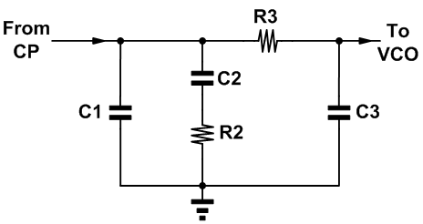
Below is the loop filter for 100kHz loop bandwidth, 26MHz reference clock, 400uA charge pump current. It has been tested and should give you around -90dBc/Hz plateau.
C1 R2 C2 R3 C3
9.01E-11 2.46E+03 1.42E-09 3280.93 2.56E-11
Loop filter components for 10kHz bandwidth, 26MHz reference clock, 400uA charge pump current are below:
C1 R2 C2 R3 C3
9.01E-09 2.46E+02 1.42E-07 328.09 2.56E-09
There should not be any issue with loop stability even with 10kHz filter. However, PLL settling time is increased so you have to slow down VCOCAP auto-tune.
I would recommend to use 100kHz filter.
Regards, Srdjan
On 22/07/2012 20:53, Andrey Sviyazov wrote:
Hi Srdjan.
First of all thank you for support.
We do not have register dump. However, Lime GUI project file used in this experiment is attached. You can use GUI File->Open Project option to import it. I see Ichp and Ichp offset currents are different from defaults but these still do not justify 5-12dB worse PN in your reports. You can give it a try though before changing TCXCO.We will try to adjust Ichp and offset first off all. Thank you for hint.
*Test Description:* * DC MAX applied through analogue inputs, DACs offIt is quite important detail too.
* TXVGA1 and TXVGA2 at max gainSimilar.
* Loop filter redesigned for 100kHz loop bandwidth and 40MHz reference * Icp and Icp offset optimized at 25 deg. Same set up used at all other temperaturesPlease inform us values of components for 100kHz BW filter. But we are forced to use one clock 26MHz for all because of target price.
* Cap code and VCO picked up by PLL tune routineI implemented 10kHz BW filter for PLL and found that frequency locking become unstable because of calculated VCOCAP value a bit lower then required (too high capacity). If VCOCAP incremented manualy (after auto-tuned) then no any problems. What do you think about it. And could you please inform me values for 10 kHz BW filter, just to compare with my calculations.
Best regards, Andrey Sviyazov.
Hi Srdjan.
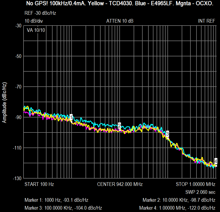
Today I found why noises and spurs are really happens in UmTRXv1.
1) Only full disabling (no power) GPS module can kill all near spurs. 2) To get good noises the next changes are required: - replace choke L6 by capacitor 10nF..0.1uF. - remove C45.
I've assembled 100kHz loop filter with the next components: C82 = 100pF, C83=1500pF, C84=33pF, R106=2.2k, R109=3.3k.
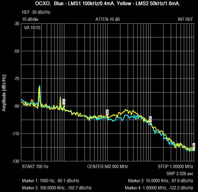
Result without GPS for IChP=0.4mA and due to several XO attached here. Also attached comparison of 50kHz/100kHz loop filters with optimal IChp 1.2mA/0.4mA but with GPS module (no antenna). So, now we need to measure integrated LO noise (degrees) to understand which filter and IChP better.
Best regards, Andrey Sviyazov.
2012/7/23 Srdjan Milenkovic s.milenkovic@limemicro.com
Hi Andrey,
Below is the loop filter for 100kHz loop bandwidth, 26MHz reference clock, 400uA charge pump current. It has been tested and should give you around -90dBc/Hz plateau.
C1 R2 C2 R3 C3 9.01E-11 2.46E+03 1.42E-09 3280.93 2.56E-11
Loop filter components for 10kHz bandwidth, 26MHz reference clock, 400uA charge pump current are below:
C1 R2 C2 R3 C3 9.01E-09 2.46E+02 1.42E-07 328.09 2.56E-09 There should not be any issue with loop stability even with 10kHz filter. However, PLL settling time is increased so you have to slow down VCOCAP auto-tune.
I would recommend to use 100kHz filter.
Regards, Srdjan
On 22/07/2012 20:53, Andrey Sviyazov wrote:
Hi Srdjan.
First of all thank you for support.
We do not have register dump. However, Lime GUI project file used in
this experiment is attached. You can use GUI File->Open Project option to import it. I see Ichp and Ichp offset currents are different from defaults but these still do not justify 5-12dB worse PN in your reports. You can give it a try though before changing TCXCO.
We will try to adjust Ichp and offset first off all. Thank you for hint.
*Test Description:*
- DC MAX applied through analogue inputs, DACs off
It is quite important detail too.
- TXVGA1 and TXVGA2 at max gain
Similar.
Loop filter redesigned for 100kHz loop bandwidth and 40MHz reference
Icp and Icp offset optimized at 25 deg. Same set up used at all
other temperatures
Please inform us values of components for 100kHz BW filter.
But we are forced to use one clock 26MHz for all because of target price.
- Cap code and VCO picked up by PLL tune routine
I implemented 10kHz BW filter for PLL and found that frequency locking
become unstable because of calculated VCOCAP value a bit lower then required (too high capacity). If VCOCAP incremented manualy (after auto-tuned) then no any problems. What do you think about it. And could you please inform me values for 10 kHz BW filter, just to compare with my calculations.
Best regards, Andrey Sviyazov.
Hi Andrey,
Plots are looking good. Just for your information, we reduced Ichp to 400uA to reduce close to integer i.e. fractional spurs which you may have not seen yet but they are there. These have noting to do with GPS module on UmTRX board neither with LMS chip, it is just PLL nature. Please be aware of this while comparing different loop filters, especially different Ichp values, ...
Best regards, Srdjan
On 23/07/2012 19:44, Andrey Sviyazov wrote:
Hi Srdjan.
Today I found why noises and spurs are really happens in UmTRXv1.
- Only full disabling (no power) GPS module can kill all near spurs.
- To get good noises the next changes are required:
- replace choke L6 by capacitor 10nF..0.1uF.
- remove C45.
I've assembled 100kHz loop filter with the next components: C82 = 100pF, C83=1500pF, C84=33pF, R106=2.2k, R109=3.3k.
Result without GPS for IChP=0.4mA and due to several XO attached here. Also attached comparison of 50kHz/100kHz loop filters with optimal IChp 1.2mA/0.4mA but with GPS module (no antenna). So, now we need to measure integrated LO noise (degrees) to understand which filter and IChP better.
Best regards, Andrey Sviyazov.
2012/7/23 Srdjan Milenkovic <s.milenkovic@limemicro.com mailto:s.milenkovic@limemicro.com>
Hi Andrey, Below is the loop filter for 100kHz loop bandwidth, 26MHz reference clock, 400uA charge pump current. It has been tested and should give you around -90dBc/Hz plateau. C1 R2 C2 R3 C3 9.01E-11 2.46E+03 1.42E-09 3280.93 2.56E-11 Loop filter components for 10kHz bandwidth, 26MHz reference clock, 400uA charge pump current are below: C1 R2 C2 R3 C3 9.01E-09 2.46E+02 1.42E-07 328.09 2.56E-09 There should not be any issue with loop stability even with 10kHz filter. However, PLL settling time is increased so you have to slow down VCOCAP auto-tune. I would recommend to use 100kHz filter. Regards, Srdjan On 22/07/2012 20:53, Andrey Sviyazov wrote:Hi Srdjan. First of all thank you for support. We do not have register dump. However, Lime GUI project file used in this experiment is attached. You can use GUI File->Open Project option to import it. I see Ichp and Ichp offset currents are different from defaults but these still do not justify 5-12dB worse PN in your reports. You can give it a try though before changing TCXCO. We will try to adjust Ichp and offset first off all. Thank you for hint. *Test Description:* * DC MAX applied through analogue inputs, DACs off It is quite important detail too. * TXVGA1 and TXVGA2 at max gain Similar. * Loop filter redesigned for 100kHz loop bandwidth and 40MHz reference * Icp and Icp offset optimized at 25 deg. Same set up used at all other temperatures Please inform us values of components for 100kHz BW filter. But we are forced to use one clock 26MHz for all because of target price. * Cap code and VCO picked up by PLL tune routine I implemented 10kHz BW filter for PLL and found that frequency locking become unstable because of calculated VCOCAP value a bit lower then required (too high capacity). If VCOCAP incremented manualy (after auto-tuned) then no any problems. What do you think about it. And could you please inform me values for 10 kHz BW filter, just to compare with my calculations. Best regards, Andrey Sviyazov.

Hi Andrey,
On Mon, Jul 23, 2012 at 10:44 PM, Andrey Sviyazov andrey.sviyazov@fairwaves.ru wrote:
Today I found why noises and spurs are really happens in UmTRXv1.
Finally, we could say UmTRX is good at phase noise.
- Only full disabling (no power) GPS module can kill all near spurs.
I wonder whether EB-570 is any better. And if EB-570 is no better - how could we protect LMS from this noise?
- To get good noises the next changes are required:
- replace choke L6 by capacitor 10nF..0.1uF.
- remove C45.
Is it possible to apply those changes for UmTRXv2 without PCB changes?
-- Regards, Alexander Chemeris. CEO, Fairwaves LLC / ООО УмРадио http://fairwaves.ru
On Tue, Jul 24, 2012 at 12:25 AM, Alexander Chemeris Alexander.Chemeris@fairwaves.ru wrote:
Hi Andrey,
On Mon, Jul 23, 2012 at 10:44 PM, Andrey Sviyazov andrey.sviyazov@fairwaves.ru wrote:
Today I found why noises and spurs are really happens in UmTRXv1.
Finally, we could say UmTRX is good at phase noise.
- Only full disabling (no power) GPS module can kill all near spurs.
I wonder whether EB-570 is any better. And if EB-570 is no better - how could we protect LMS from this noise?
- To get good noises the next changes are required:
- replace choke L6 by capacitor 10nF..0.1uF.
- remove C45.
Is it possible to apply those changes for UmTRXv2 without PCB changes?
PS Please add both points to the tracker, so we don't forget.
-
 Alexander Chemeris
 -
 Alexander Chemeris
 -
 Andrey Sviyazov
 -
 Andrey Sviyazov
 -
 Srdjan Milenkovic