
Hi Alexander,
These last days, I tried to find a solution for the selectivity improvement.
I have 5 solutions to propose. 1st and 2nd are inboard solutions. 3rd, 4th and 5th uses an external board. Some seems to be much better than others.
1/ We could use an IF frequency above 375 MHz to be able to connect the IF signal dirtectly to the LMS, without any upconvertion back to RF frequency. This would save some components. We could use the ADRF6601 (PLL/VCO + mixer) and the TB0448A IF SAW filter. The ADRF6601 is single chip PLL/VCO and mixer. This would be quite convenient. The TB0448A is cheap (< 3 USD), narrow band (good selectivity) and 400 MHz center frequency (> 375 MHz LMS lower limit).
Cost of this solution would be about 60 USD and selectivity would be really good. The main disadvantage of this solution is the filter would restrict the signal to a single GSM carrier. This would avoid us to get both GSM carriers on each LMS. We would not be able to get true diversity. We would only be able to get switched diversity.
After the LNA, RF SAW filter and the RF switches, we can split the signal between the current RX path to LMS RX LNA 3 and a new alternate RX path (ADRF6601 => TB0448A => LMS RX LNA 1). Depending of our need for selectivity, we would be able to select 1 of these 2 RX path (direct RX path to LMS RX LNA 3 or IF filter RX path to LMS RX LNA1).
This would allow to use the board either as a normal wideband SDR board or with a very selective filter.
2/ A very nice option would be to use a variant of the 1st solution with a wider bandwidth SAW IF filter. For example, if we use a 400 to 600 KHz bandwidth IF filter, we would also get a very good selectivity and we would also be able to sample both GSM carriers on each LMS. This would allow a good selectivity and full diversity.
The problem is we would need a 400 to 600 KHz SAW IF filter, with good selectivity, reasonable price and an IF center frequency above 375 MHz. I was not able to find such a filter.
3/ As suggested a few days ago, we may use the external selectivity improvement board design I sent you. Instead of the Triquint 856378 IF SAW filter, we could use the TAISAW TB0448A narrow band filter. This TAISAW filter is really much cheaper than the Triquint. This would save a lot of budget. However, we would still need 4 mixer and 2 PLL/VCO for each LMS RX path. This external board would cost approximately 100 USD (excluding PCB and assembly). We would need 2 of these boards for each UmTRX board. This would make 200 USD per UmTRX. Including PCB and assembly, toatl cost would be around 300 USD. This is not compeltely unrealistic but it seems still quite expensive.
4/ Another solution would be to build a single carrier version of the 3rd solution design. We would need only 1 RF path (PLL/VCO + mixer) with only 1 narrow band filter per LMS RX path. This would not need any splitter or combiner. Design would be quite simple and cost would be about 2 times lower. However, as we will have only 1 carrier on each antenna, we would not be able to get diversity at all.
This solution would finally not have many advantages compared to 1st solution. It would cost more and would not allow any kind of diversity.
5/ Last solution would be to build an external diversity improvement board, as 4th solution, but with a wider band IF SAW filter.
We could use the following RF path: LNA => RF SAW filter => mixer => IF SAW filter => mixer => RF SAW filter. Dual mixer could be the ADL5802 connected to the ADF4350 PLL/VCO.
We could use the TB0218A IF SAW filter. This filter is quite affordable (< 10 USD). Selectivity is good and bandwidth is wide enough to select 2 GSM carriers (separated by 400 KHz).
Cost of such external diversity improvement board would be quite reasonable. This would be a very nice solution to select 2 GSM carriers. Connected to the UmTRX, this selectivity improvement board would allow to get both switched or true diversity.
As TB0218A center frequency is 140 MHz, we would not be able to connect directly the IF signal to the LMS. We would need to up convert the signal back to the RF frequency. As IF down converted signal is upconverted back to the original RF frequency, it would be possible to use this selectivity improvement board with any kind of existing OpenBTS (UmTRX, USRP, SSRP...) or OpenBSC (Sysmocom BTS, IP.access nanoBTS...) hardware to improve the Rx selectivity. This would offer a wider potential market than an inboard solution.
Considering all these solution, I believe 1st and 5th solutions seems to be the best choices. 2nd solution would also be really nice but I was not able to find the appropriate IF SAW filter. Please let me know your opinion regarding each of these two solutions.
By the way, the TB0448A and TB0218A SAW filters looks really good but I am not 100% sure the GSM carrier spectrum distortion due to the pass band ripple of the SAW filter is acceptable. Center part of the GSM carrier (f +/- 100 KHz) is fine but side parts of the GSM carrier (bellow f - 100 KHz and above f + 100 KHz) may be cut a bit by the SAW filter.
Could you also please check the TB0448A and TB0218A datasheets to double check if the usable bandwidth is wide enough ? Especially, do you think cutting a bit the side parts of the GSM carrier may cause problem ?
Anyway, please let me know your point of view regarding these selectivity improvement solutions.
Best regards.
Jean-Samuel. :-)

Hi all!
I am again about far-near problem.
If we have heterodyne noise -135dBc/Hz at 600kHz offset (ADRF6601), then for blocking signal at the same offset and at 200kHz RBW we get additional noise level 135-53=72dBc relative to blocking signal level. To keep "normal GSM900 BS" sensitivity -104dBm we must keep additional noise as low as -107dBm, therefore blocking signal maximum level must less then -107+73=-39dBm. But in GSM-05.05 (sec 5.1) I saw blocking characteristics requirements for normal BTS must be -26 dBm at 0.6-0.8 MHz offset and -16 dBm at 0.8-1.6 MHz offset. So, I do not know how and who can meet those requirements and I am really hope that there are fundamental mistakes in my calculations. Correct me please.
Best regards, Andrey Sviyazov.
16 января 2012 г. 19:22 пользователь Jean-Samuel Najnudel - BJT PARTNERS SARL jsn@bjtpartners.com написал:
Hi Alexander,
These last days, I tried to find a solution for the selectivity improvement.
I have 5 solutions to propose. 1st and 2nd are inboard solutions. 3rd, 4th and 5th uses an external board. Some seems to be much better than others.
1/ We could use an IF frequency above 375 MHz to be able to connect the IF signal dirtectly to the LMS, without any upconvertion back to RF frequency. This would save some components. We could use the ADRF6601 (PLL/VCO + mixer) and the TB0448A IF SAW filter. The ADRF6601 is single chip PLL/VCO and mixer. This would be quite convenient. The TB0448A is cheap (< 3 USD), narrow band (good selectivity) and 400 MHz center frequency (> 375 MHz LMS lower limit).
Cost of this solution would be about 60 USD and selectivity would be really good. The main disadvantage of this solution is the filter would restrict the signal to a single GSM carrier. This would avoid us to get both GSM carriers on each LMS. We would not be able to get true diversity. We would only be able to get switched diversity.
After the LNA, RF SAW filter and the RF switches, we can split the signal between the current RX path to LMS RX LNA 3 and a new alternate RX path (ADRF6601 => TB0448A => LMS RX LNA 1). Depending of our need for selectivity, we would be able to select 1 of these 2 RX path (direct RX path to LMS RX LNA 3 or IF filter RX path to LMS RX LNA1).
This would allow to use the board either as a normal wideband SDR board or with a very selective filter.
2/ A very nice option would be to use a variant of the 1st solution with a wider bandwidth SAW IF filter. For example, if we use a 400 to 600 KHz bandwidth IF filter, we would also get a very good selectivity and we would also be able to sample both GSM carriers on each LMS. This would allow a good selectivity and full diversity.
The problem is we would need a 400 to 600 KHz SAW IF filter, with good selectivity, reasonable price and an IF center frequency above 375 MHz. I was not able to find such a filter.
3/ As suggested a few days ago, we may use the external selectivity improvement board design I sent you. Instead of the Triquint 856378 IF SAW filter, we could use the TAISAW TB0448A narrow band filter. This TAISAW filter is really much cheaper than the Triquint. This would save a lot of budget. However, we would still need 4 mixer and 2 PLL/VCO for each LMS RX path. This external board would cost approximately 100 USD (excluding PCB and assembly). We would need 2 of these boards for each UmTRX board. This would make 200 USD per UmTRX. Including PCB and assembly, toatl cost would be around 300 USD. This is not compeltely unrealistic but it seems still quite expensive.
4/ Another solution would be to build a single carrier version of the 3rd solution design. We would need only 1 RF path (PLL/VCO + mixer) with only 1 narrow band filter per LMS RX path. This would not need any splitter or combiner. Design would be quite simple and cost would be about 2 times lower. However, as we will have only 1 carrier on each antenna, we would not be able to get diversity at all.
This solution would finally not have many advantages compared to 1st solution. It would cost more and would not allow any kind of diversity.
5/ Last solution would be to build an external diversity improvement board, as 4th solution, but with a wider band IF SAW filter.
We could use the following RF path: LNA => RF SAW filter => mixer => IF SAW filter => mixer => RF SAW filter. Dual mixer could be the ADL5802 connected to the ADF4350 PLL/VCO.
We could use the TB0218A IF SAW filter. This filter is quite affordable (< 10 USD). Selectivity is good and bandwidth is wide enough to select 2 GSM carriers (separated by 400 KHz).
Cost of such external diversity improvement board would be quite reasonable. This would be a very nice solution to select 2 GSM carriers. Connected to the UmTRX, this selectivity improvement board would allow to get both switched or true diversity.
As TB0218A center frequency is 140 MHz, we would not be able to connect directly the IF signal to the LMS. We would need to up convert the signal back to the RF frequency. As IF down converted signal is upconverted back to the original RF frequency, it would be possible to use this selectivity improvement board with any kind of existing OpenBTS (UmTRX, USRP, SSRP...) or OpenBSC (Sysmocom BTS, IP.access nanoBTS...) hardware to improve the Rx selectivity. This would offer a wider potential market than an inboard solution.
Considering all these solution, I believe 1st and 5th solutions seems to be the best choices. 2nd solution would also be really nice but I was not able to find the appropriate IF SAW filter. Please let me know your opinion regarding each of these two solutions.
By the way, the TB0448A and TB0218A SAW filters looks really good but I am not 100% sure the GSM carrier spectrum distortion due to the pass band ripple of the SAW filter is acceptable. Center part of the GSM carrier (f +/- 100 KHz) is fine but side parts of the GSM carrier (bellow f - 100 KHz and above f + 100 KHz) may be cut a bit by the SAW filter.
Could you also please check the TB0448A and TB0218A datasheets to double check if the usable bandwidth is wide enough ? Especially, do you think cutting a bit the side parts of the GSM carrier may cause problem ?
Anyway, please let me know your point of view regarding these selectivity improvement solutions.
Best regards.
Jean-Samuel. :-)
Hi Andrey,
Thank you for your e-mail.
Yes, you are all right.
It think your calculations are good. I just did not knew how hard was the GSM macro BTS spec.
I browsed a bit the web and found the GSM 05.05 specs which confirm what you say. I also found some similar information and calculations in an academic paper which confirm your figures. http://www.uta.edu/rfmems/Conferences/2001_SPIE_MicroMEMS/4592-20.pdf (page 5 and 6)
Anyway, I tried to look at other components than the ADRF6601.
I found a quite low phase noise VCO/PLL from Hittite which seems to be able to let us probably pass the macro BTS spec or at least the micro BTS spec. http://www.hittite.com/products/view.html/view/HMC830LP6GE
For the mixer, we may use a separate component like the ADL5801.
Please let me know what you think about these chips. Please do not hesitate to let us know some other suggestions if you know or if you can find some other components that would have better performances.
Actually, even if the specs are not easy to pass, I still feel quite optimistic as it was possible to pass these specs 15 years old components. Anyway, if the macro BTS specs are really too hard to pass, we may focus on the micro BTS spec. This would already be great to convince the market you may be interested in and the performances would be good enough for most practical situations in my deployment in Mayotte.
Best regards.
Jean-Samuel. :-)
2012/3/14 Andrey Sviyazov andreysviyaz@gmail.com
Hi all!
I am again about far-near problem.
If we have heterodyne noise -135dBc/Hz at 600kHz offset (ADRF6601), then for blocking signal at the same offset and at 200kHz RBW we get additional noise level 135-53=72dBc relative to blocking signal level. To keep "normal GSM900 BS" sensitivity -104dBm we must keep additional noise as low as -107dBm, therefore blocking signal maximum level must less then -107+73=-39dBm. But in GSM-05.05 (sec 5.1) I saw blocking characteristics requirements for normal BTS must be -26 dBm at 0.6-0.8 MHz offset and -16 dBm at 0.8-1.6 MHz offset. So, I do not know how and who can meet those requirements and I am really hope that there are fundamental mistakes in my calculations. Correct me please.
Best regards, Andrey Sviyazov.
16 января 2012 г. 19:22 пользователь Jean-Samuel Najnudel - BJT PARTNERS SARL jsn@bjtpartners.com написал:
Hi Alexander,
These last days, I tried to find a solution for the selectivity improvement.
I have 5 solutions to propose. 1st and 2nd are inboard solutions. 3rd, 4th and 5th uses an external board. Some seems to be much better than others.
1/ We could use an IF frequency above 375 MHz to be able to connect the IF signal dirtectly to the LMS, without any upconvertion back to RF frequency. This would save some components. We could use the ADRF6601 (PLL/VCO + mixer) and the TB0448A IF SAW filter. The ADRF6601 is single chip PLL/VCO and mixer. This would be quite convenient. The TB0448A is cheap (< 3 USD), narrow band (good selectivity) and 400 MHz center frequency (> 375 MHz LMS lower limit).
Cost of this solution would be about 60 USD and selectivity would be really good. The main disadvantage of this solution is the filter would restrict the signal to a single GSM carrier. This would avoid us to get both GSM carriers on each LMS. We would not be able to get true diversity. We would only be able to get switched diversity.
After the LNA, RF SAW filter and the RF switches, we can split the signal between the current RX path to LMS RX LNA 3 and a new alternate RX path (ADRF6601 => TB0448A => LMS RX LNA 1). Depending of our need for selectivity, we would be able to select 1 of these 2 RX path (direct RX path to LMS RX LNA 3 or IF filter RX path to LMS RX LNA1).
This would allow to use the board either as a normal wideband SDR board or with a very selective filter.
2/ A very nice option would be to use a variant of the 1st solution with a wider bandwidth SAW IF filter. For example, if we use a 400 to 600 KHz bandwidth IF filter, we would also get a very good selectivity and we would also be able to sample both GSM carriers on each LMS. This would allow a good selectivity and full diversity.
The problem is we would need a 400 to 600 KHz SAW IF filter, with good selectivity, reasonable price and an IF center frequency above 375 MHz. I was not able to find such a filter.
3/ As suggested a few days ago, we may use the external selectivity improvement board design I sent you. Instead of the Triquint 856378 IF SAW filter, we could use the TAISAW TB0448A narrow band filter. This TAISAW filter is really much cheaper than the Triquint. This would save a lot of budget. However, we would still need 4 mixer and 2 PLL/VCO for each LMS RX path. This external board would cost approximately 100 USD (excluding PCB and assembly). We would need 2 of these boards for each UmTRX board. This would make 200 USD per UmTRX. Including PCB and assembly, toatl cost would be around 300 USD. This is not compeltely unrealistic but it seems still quite expensive.
4/ Another solution would be to build a single carrier version of the 3rd solution design. We would need only 1 RF path (PLL/VCO + mixer) with only 1 narrow band filter per LMS RX path. This would not need any splitter or combiner. Design would be quite simple and cost would be about 2 times lower. However, as we will have only 1 carrier on each antenna, we would not be able to get diversity at all.
This solution would finally not have many advantages compared to 1st solution. It would cost more and would not allow any kind of diversity.
5/ Last solution would be to build an external diversity improvement board, as 4th solution, but with a wider band IF SAW filter.
We could use the following RF path: LNA => RF SAW filter => mixer => IF SAW filter => mixer => RF SAW filter. Dual mixer could be the ADL5802 connected to the ADF4350 PLL/VCO.
We could use the TB0218A IF SAW filter. This filter is quite affordable (< 10 USD). Selectivity is good and bandwidth is wide enough to select 2 GSM carriers (separated by 400 KHz).
Cost of such external diversity improvement board would be quite reasonable. This would be a very nice solution to select 2 GSM carriers. Connected to the UmTRX, this selectivity improvement board would allow to get both switched or true diversity.
As TB0218A center frequency is 140 MHz, we would not be able to connect directly the IF signal to the LMS. We would need to up convert the signal back to the RF frequency. As IF down converted signal is upconverted back to the original RF frequency, it would be possible to use this selectivity improvement board with any kind of existing OpenBTS (UmTRX, USRP, SSRP...) or OpenBSC (Sysmocom BTS, IP.access nanoBTS...) hardware to improve the Rx selectivity. This would offer a wider potential market than an inboard solution.
Considering all these solution, I believe 1st and 5th solutions seems to be the best choices. 2nd solution would also be really nice but I was not able to find the appropriate IF SAW filter. Please let me know your opinion regarding each of these two solutions.
By the way, the TB0448A and TB0218A SAW filters looks really good but I am not 100% sure the GSM carrier spectrum distortion due to the pass band ripple of the SAW filter is acceptable. Center part of the GSM carrier (f +/- 100 KHz) is fine but side parts of the GSM carrier (bellow f - 100 KHz and above f + 100 KHz) may be cut a bit by the SAW filter.
Could you also please check the TB0448A and TB0218A datasheets to double check if the usable bandwidth is wide enough ? Especially, do you think cutting a bit the side parts of the GSM carrier may cause problem ?
Anyway, please let me know your point of view regarding these selectivity improvement solutions.
Best regards.
Jean-Samuel. :-)
Hi Jean-Samuel!
About ADL5802, you can't use it as Down and Up converter simultaneously. Also I'm afraid that we can't yet receiving 2 GSM carriers simultaneously. So lets done single channel first but 2 or more keep in mind for experiments.
I try to find better components too. ADI mixers have internal IF AMP and it is not good in this case. Components of Hittite are known for me as a very good through my main job. I'd like to recommend to use any of the next: for GSM900 1/ HMC830LP6GE + HMC483MS8GE + TB0130A. (20.6+4.69+3=$28.29) 2/ HMC830LP6GE + HMC686LP4E + TB0448A. (20.6+9.67+3=$32.97) for DCS1800 1/ HMC830LP6GE + HMC485MS8GE + TB0130A . (20.6+4.69+3=$28.29) 2/ HMC830LP6GE + HMC687LP4E + TB0448A. (20.6+9.67+3=$32.97) By the way, LMS lower limit 0.3GHz as per datasheet.
About GSM 05.05 specs I still can't understand blocker requirements: MS spectrum with RBW=200kHz have -65dBc level at 600-1200kHz offset, therefore blocker MS with -26dBm will be jammer for wanted MS with level less then -91dBm and noise level of receiver's heterodyne isn't matter in this case. I really can't understand why CW levels -26dBm and -16dBm blocking tests required. May be it just universal test of heterodyne quality?
I think we should be reasonable people, and therefore we should use parameters which really necessary for us. So, ADRF6601 parameters seems to be quite enough even if it pass only mBS requirements. On the other hand, BOM difference between ADRF and HMC's around $20-25 only and it isn't much for normal BS. In short, it seems that we should do three options front-end mezzanines: 1/ without channel preselector for picoBS or nanoBS upto 0.5W/ch. 2/ preselector ADRF based for microBS upto 2W/ch. 3/ preselector HMC based for normal BS with 10-20W/ch TMB.
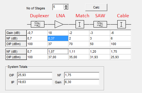
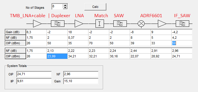
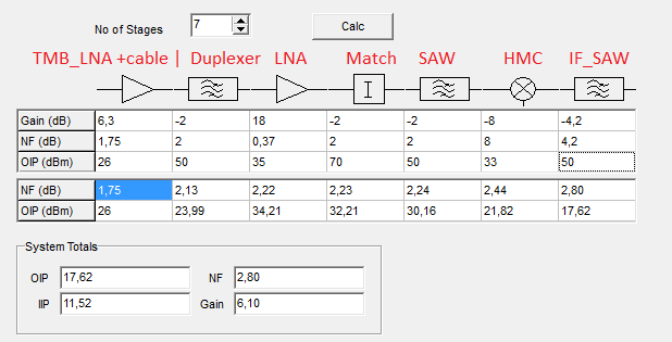
Please find attached pictures that my simple calculations for RX chain. Also, please let me know real PA parameters which you decide to use for TMB.
Best regards, Andrey Sviyazov.
15 марта 2012 г. 4:42 пользователь Jean-Samuel Najnudel - BJT PARTNERS SARL jsn@bjtpartners.com написал:
Hi Andrey,
Thank you for your e-mail.
Yes, you are all right.
It think your calculations are good. I just did not knew how hard was the GSM macro BTS spec.
I browsed a bit the web and found the GSM 05.05 specs which confirm what you say. I also found some similar information and calculations in an academic paper which confirm your figures. http://www.uta.edu/rfmems/Conferences/2001_SPIE_MicroMEMS/4592-20.pdf(page 5 and 6)
Anyway, I tried to look at other components than the ADRF6601.
I found a quite low phase noise VCO/PLL from Hittite which seems to be able to let us probably pass the macro BTS spec or at least the micro BTS spec. http://www.hittite.com/products/view.html/view/HMC830LP6GE
For the mixer, we may use a separate component like the ADL5801.
Please let me know what you think about these chips. Please do not hesitate to let us know some other suggestions if you know or if you can find some other components that would have better performances.
Actually, even if the specs are not easy to pass, I still feel quite optimistic as it was possible to pass these specs 15 years old components. Anyway, if the macro BTS specs are really too hard to pass, we may focus on the micro BTS spec. This would already be great to convince the market you may be interested in and the performances would be good enough for most practical situations in my deployment in Mayotte.
Best regards.
Jean-Samuel. :-)
2012/3/14 Andrey Sviyazov andreysviyaz@gmail.com
Hi all!
I am again about far-near problem.
If we have heterodyne noise -135dBc/Hz at 600kHz offset (ADRF6601), then for blocking signal at the same offset and at 200kHz RBW we get additional noise level 135-53=72dBc relative to blocking signal level. To keep "normal GSM900 BS" sensitivity -104dBm we must keep additional noise as low as -107dBm, therefore blocking signal maximum level must less then -107+73=-39dBm. But in GSM-05.05 (sec 5.1) I saw blocking characteristics requirements for normal BTS must be -26 dBm at 0.6-0.8 MHz offset and -16 dBm at 0.8-1.6 MHz offset. So, I do not know how and who can meet those requirements and I am really hope that there are fundamental mistakes in my calculations. Correct me please.
Best regards, Andrey Sviyazov.
16 января 2012 г. 19:22 пользователь Jean-Samuel Najnudel - BJT PARTNERS SARL jsn@bjtpartners.com написал:
Hi Alexander,
These last days, I tried to find a solution for the selectivity improvement.
I have 5 solutions to propose. 1st and 2nd are inboard solutions. 3rd, 4th and 5th uses an external board. Some seems to be much better than others.
1/ We could use an IF frequency above 375 MHz to be able to connect the IF signal dirtectly to the LMS, without any upconvertion back to RF frequency. This would save some components. We could use the ADRF6601 (PLL/VCO + mixer) and the TB0448A IF SAW filter. The ADRF6601 is single chip PLL/VCO and mixer. This would be quite convenient. The TB0448A is cheap (< 3 USD), narrow band (good selectivity) and 400 MHz center frequency (> 375 MHz LMS lower limit).
Cost of this solution would be about 60 USD and selectivity would be really good. The main disadvantage of this solution is the filter would restrict the signal to a single GSM carrier. This would avoid us to get both GSM carriers on each LMS. We would not be able to get true diversity. We would only be able to get switched diversity.
After the LNA, RF SAW filter and the RF switches, we can split the signal between the current RX path to LMS RX LNA 3 and a new alternate RX path (ADRF6601 => TB0448A => LMS RX LNA 1). Depending of our need for selectivity, we would be able to select 1 of these 2 RX path (direct RX path to LMS RX LNA 3 or IF filter RX path to LMS RX LNA1).
This would allow to use the board either as a normal wideband SDR board or with a very selective filter.
2/ A very nice option would be to use a variant of the 1st solution with a wider bandwidth SAW IF filter. For example, if we use a 400 to 600 KHz bandwidth IF filter, we would also get a very good selectivity and we would also be able to sample both GSM carriers on each LMS. This would allow a good selectivity and full diversity.
The problem is we would need a 400 to 600 KHz SAW IF filter, with good selectivity, reasonable price and an IF center frequency above 375 MHz. I was not able to find such a filter.
3/ As suggested a few days ago, we may use the external selectivity improvement board design I sent you. Instead of the Triquint 856378 IF SAW filter, we could use the TAISAW TB0448A narrow band filter. This TAISAW filter is really much cheaper than the Triquint. This would save a lot of budget. However, we would still need 4 mixer and 2 PLL/VCO for each LMS RX path. This external board would cost approximately 100 USD (excluding PCB and assembly). We would need 2 of these boards for each UmTRX board. This would make 200 USD per UmTRX. Including PCB and assembly, toatl cost would be around 300 USD. This is not compeltely unrealistic but it seems still quite expensive.
4/ Another solution would be to build a single carrier version of the 3rd solution design. We would need only 1 RF path (PLL/VCO + mixer) with only 1 narrow band filter per LMS RX path. This would not need any splitter or combiner. Design would be quite simple and cost would be about 2 times lower. However, as we will have only 1 carrier on each antenna, we would not be able to get diversity at all.
This solution would finally not have many advantages compared to 1st solution. It would cost more and would not allow any kind of diversity.
5/ Last solution would be to build an external diversity improvement board, as 4th solution, but with a wider band IF SAW filter.
We could use the following RF path: LNA => RF SAW filter => mixer => IF SAW filter => mixer => RF SAW filter. Dual mixer could be the ADL5802 connected to the ADF4350 PLL/VCO.
We could use the TB0218A IF SAW filter. This filter is quite affordable (< 10 USD). Selectivity is good and bandwidth is wide enough to select 2 GSM carriers (separated by 400 KHz).
Cost of such external diversity improvement board would be quite reasonable. This would be a very nice solution to select 2 GSM carriers. Connected to the UmTRX, this selectivity improvement board would allow to get both switched or true diversity.
As TB0218A center frequency is 140 MHz, we would not be able to connect directly the IF signal to the LMS. We would need to up convert the signal back to the RF frequency. As IF down converted signal is upconverted back to the original RF frequency, it would be possible to use this selectivity improvement board with any kind of existing OpenBTS (UmTRX, USRP, SSRP...) or OpenBSC (Sysmocom BTS, IP.access nanoBTS...) hardware to improve the Rx selectivity. This would offer a wider potential market than an inboard solution.
Considering all these solution, I believe 1st and 5th solutions seems to be the best choices. 2nd solution would also be really nice but I was not able to find the appropriate IF SAW filter. Please let me know your opinion regarding each of these two solutions.
By the way, the TB0448A and TB0218A SAW filters looks really good but I am not 100% sure the GSM carrier spectrum distortion due to the pass band ripple of the SAW filter is acceptable. Center part of the GSM carrier (f +/- 100 KHz) is fine but side parts of the GSM carrier (bellow f - 100 KHz and above f + 100 KHz) may be cut a bit by the SAW filter.
Could you also please check the TB0448A and TB0218A datasheets to double check if the usable bandwidth is wide enough ? Especially, do you think cutting a bit the side parts of the GSM carrier may cause problem ?
Anyway, please let me know your point of view regarding these selectivity improvement solutions.
Best regards.
Jean-Samuel. :-)

Hittite is located in Massachusetts about 40 km from Boston. Let me know if I can help with sourcing components or requesting samples.
-Robin -----Original Message----- From: Andrey Sviyazov andreysviyaz@gmail.com Date: Fri, 16 Mar 2012 02:54:51 To: Jean-Samuel Najnudel - BJT PARTNERS SARLjsn@bjtpartners.com Cc: Alexander Chemerisalexander.chemeris@gmail.com; gsm-internal@lists.fairwaves.ru; Robin Coxecoxe@close-haul.com; Project Mayotteproject-mayotte@sysmocom.de Subject: Re: Selectivity improvement solutions proposal for UmTRX
Hi Jean-Samuel!
About ADL5802, you can't use it as Down and Up converter simultaneously. Also I'm afraid that we can't yet receiving 2 GSM carriers simultaneously. So lets done single channel first but 2 or more keep in mind for experiments.
I try to find better components too. ADI mixers have internal IF AMP and it is not good in this case. Components of Hittite are known for me as a very good through my main job. I'd like to recommend to use any of the next: for GSM900 1/ HMC830LP6GE + HMC483MS8GE + TB0130A. (20.6+4.69+3=$28.29) 2/ HMC830LP6GE + HMC686LP4E + TB0448A. (20.6+9.67+3=$32.97) for DCS1800 1/ HMC830LP6GE + HMC485MS8GE + TB0130A . (20.6+4.69+3=$28.29) 2/ HMC830LP6GE + HMC687LP4E + TB0448A. (20.6+9.67+3=$32.97) By the way, LMS lower limit 0.3GHz as per datasheet.
About GSM 05.05 specs I still can't understand blocker requirements: MS spectrum with RBW=200kHz have -65dBc level at 600-1200kHz offset, therefore blocker MS with -26dBm will be jammer for wanted MS with level less then -91dBm and noise level of receiver's heterodyne isn't matter in this case. I really can't understand why CW levels -26dBm and -16dBm blocking tests required. May be it just universal test of heterodyne quality?
I think we should be reasonable people, and therefore we should use parameters which really necessary for us. So, ADRF6601 parameters seems to be quite enough even if it pass only mBS requirements. On the other hand, BOM difference between ADRF and HMC's around $20-25 only and it isn't much for normal BS. In short, it seems that we should do three options front-end mezzanines: 1/ without channel preselector for picoBS or nanoBS upto 0.5W/ch. 2/ preselector ADRF based for microBS upto 2W/ch. 3/ preselector HMC based for normal BS with 10-20W/ch TMB.
Please find attached pictures that my simple calculations for RX chain. Also, please let me know real PA parameters which you decide to use for TMB.
Best regards, Andrey Sviyazov.
15 марта 2012 г. 4:42 пользователь Jean-Samuel Najnudel - BJT PARTNERS SARL jsn@bjtpartners.com написал:
Hi Andrey,
Thank you for your e-mail.
Yes, you are all right.
It think your calculations are good. I just did not knew how hard was the GSM macro BTS spec.
I browsed a bit the web and found the GSM 05.05 specs which confirm what you say. I also found some similar information and calculations in an academic paper which confirm your figures. http://www.uta.edu/rfmems/Conferences/2001_SPIE_MicroMEMS/4592-20.pdf(page 5 and 6)
Anyway, I tried to look at other components than the ADRF6601.
I found a quite low phase noise VCO/PLL from Hittite which seems to be able to let us probably pass the macro BTS spec or at least the micro BTS spec. http://www.hittite.com/products/view.html/view/HMC830LP6GE
For the mixer, we may use a separate component like the ADL5801.
Please let me know what you think about these chips. Please do not hesitate to let us know some other suggestions if you know or if you can find some other components that would have better performances.
Actually, even if the specs are not easy to pass, I still feel quite optimistic as it was possible to pass these specs 15 years old components. Anyway, if the macro BTS specs are really too hard to pass, we may focus on the micro BTS spec. This would already be great to convince the market you may be interested in and the performances would be good enough for most practical situations in my deployment in Mayotte.
Best regards.
Jean-Samuel. :-)
2012/3/14 Andrey Sviyazov andreysviyaz@gmail.com
Hi all!
I am again about far-near problem.
If we have heterodyne noise -135dBc/Hz at 600kHz offset (ADRF6601), then for blocking signal at the same offset and at 200kHz RBW we get additional noise level 135-53=72dBc relative to blocking signal level. To keep "normal GSM900 BS" sensitivity -104dBm we must keep additional noise as low as -107dBm, therefore blocking signal maximum level must less then -107+73=-39dBm. But in GSM-05.05 (sec 5.1) I saw blocking characteristics requirements for normal BTS must be -26 dBm at 0.6-0.8 MHz offset and -16 dBm at 0.8-1.6 MHz offset. So, I do not know how and who can meet those requirements and I am really hope that there are fundamental mistakes in my calculations. Correct me please.
Best regards, Andrey Sviyazov.
16 января 2012 г. 19:22 пользователь Jean-Samuel Najnudel - BJT PARTNERS SARL jsn@bjtpartners.com написал:
Hi Alexander,
These last days, I tried to find a solution for the selectivity improvement.
I have 5 solutions to propose. 1st and 2nd are inboard solutions. 3rd, 4th and 5th uses an external board. Some seems to be much better than others.
1/ We could use an IF frequency above 375 MHz to be able to connect the IF signal dirtectly to the LMS, without any upconvertion back to RF frequency. This would save some components. We could use the ADRF6601 (PLL/VCO + mixer) and the TB0448A IF SAW filter. The ADRF6601 is single chip PLL/VCO and mixer. This would be quite convenient. The TB0448A is cheap (< 3 USD), narrow band (good selectivity) and 400 MHz center frequency (> 375 MHz LMS lower limit).
Cost of this solution would be about 60 USD and selectivity would be really good. The main disadvantage of this solution is the filter would restrict the signal to a single GSM carrier. This would avoid us to get both GSM carriers on each LMS. We would not be able to get true diversity. We would only be able to get switched diversity.
After the LNA, RF SAW filter and the RF switches, we can split the signal between the current RX path to LMS RX LNA 3 and a new alternate RX path (ADRF6601 => TB0448A => LMS RX LNA 1). Depending of our need for selectivity, we would be able to select 1 of these 2 RX path (direct RX path to LMS RX LNA 3 or IF filter RX path to LMS RX LNA1).
This would allow to use the board either as a normal wideband SDR board or with a very selective filter.
2/ A very nice option would be to use a variant of the 1st solution with a wider bandwidth SAW IF filter. For example, if we use a 400 to 600 KHz bandwidth IF filter, we would also get a very good selectivity and we would also be able to sample both GSM carriers on each LMS. This would allow a good selectivity and full diversity.
The problem is we would need a 400 to 600 KHz SAW IF filter, with good selectivity, reasonable price and an IF center frequency above 375 MHz. I was not able to find such a filter.
3/ As suggested a few days ago, we may use the external selectivity improvement board design I sent you. Instead of the Triquint 856378 IF SAW filter, we could use the TAISAW TB0448A narrow band filter. This TAISAW filter is really much cheaper than the Triquint. This would save a lot of budget. However, we would still need 4 mixer and 2 PLL/VCO for each LMS RX path. This external board would cost approximately 100 USD (excluding PCB and assembly). We would need 2 of these boards for each UmTRX board. This would make 200 USD per UmTRX. Including PCB and assembly, toatl cost would be around 300 USD. This is not compeltely unrealistic but it seems still quite expensive.
4/ Another solution would be to build a single carrier version of the 3rd solution design. We would need only 1 RF path (PLL/VCO + mixer) with only 1 narrow band filter per LMS RX path. This would not need any splitter or combiner. Design would be quite simple and cost would be about 2 times lower. However, as we will have only 1 carrier on each antenna, we would not be able to get diversity at all.
This solution would finally not have many advantages compared to 1st solution. It would cost more and would not allow any kind of diversity.
5/ Last solution would be to build an external diversity improvement board, as 4th solution, but with a wider band IF SAW filter.
We could use the following RF path: LNA => RF SAW filter => mixer => IF SAW filter => mixer => RF SAW filter. Dual mixer could be the ADL5802 connected to the ADF4350 PLL/VCO.
We could use the TB0218A IF SAW filter. This filter is quite affordable (< 10 USD). Selectivity is good and bandwidth is wide enough to select 2 GSM carriers (separated by 400 KHz).
Cost of such external diversity improvement board would be quite reasonable. This would be a very nice solution to select 2 GSM carriers. Connected to the UmTRX, this selectivity improvement board would allow to get both switched or true diversity.
As TB0218A center frequency is 140 MHz, we would not be able to connect directly the IF signal to the LMS. We would need to up convert the signal back to the RF frequency. As IF down converted signal is upconverted back to the original RF frequency, it would be possible to use this selectivity improvement board with any kind of existing OpenBTS (UmTRX, USRP, SSRP...) or OpenBSC (Sysmocom BTS, IP.access nanoBTS...) hardware to improve the Rx selectivity. This would offer a wider potential market than an inboard solution.
Considering all these solution, I believe 1st and 5th solutions seems to be the best choices. 2nd solution would also be really nice but I was not able to find the appropriate IF SAW filter. Please let me know your opinion regarding each of these two solutions.
By the way, the TB0448A and TB0218A SAW filters looks really good but I am not 100% sure the GSM carrier spectrum distortion due to the pass band ripple of the SAW filter is acceptable. Center part of the GSM carrier (f +/- 100 KHz) is fine but side parts of the GSM carrier (bellow f - 100 KHz and above f + 100 KHz) may be cut a bit by the SAW filter.
Could you also please check the TB0448A and TB0218A datasheets to double check if the usable bandwidth is wide enough ? Especially, do you think cutting a bit the side parts of the GSM carrier may cause problem ?
Anyway, please let me know your point of view regarding these selectivity improvement solutions.
Best regards.
Jean-Samuel. :-)
Hi Robin,
Thank you very much for your help. This could be very convenient. Thanks a lot.
Best regards.
Jean-Samuel. :-)
On Fri, Mar 16, 2012 at 12:08 AM, Robin Coxe coxe@close-haul.com wrote:
** Hittite is located in Massachusetts about 40 km from Boston. Let me know if I can help with sourcing components or requesting samples.
-Robin
*From: * Andrey Sviyazov andreysviyaz@gmail.com *Date: *Fri, 16 Mar 2012 02:54:51 +0400 *To: *Jean-Samuel Najnudel - BJT PARTNERS SARLjsn@bjtpartners.com *Cc: *Alexander Chemerisalexander.chemeris@gmail.com; < gsm-internal@lists.fairwaves.ru>; Robin Coxecoxe@close-haul.com; Project Mayotteproject-mayotte@sysmocom.de *Subject: *Re: Selectivity improvement solutions proposal for UmTRX
Hi Jean-Samuel!
About ADL5802, you can't use it as Down and Up converter simultaneously. Also I'm afraid that we can't yet receiving 2 GSM carriers simultaneously. So lets done single channel first but 2 or more keep in mind for experiments.
I try to find better components too. ADI mixers have internal IF AMP and it is not good in this case. Components of Hittite are known for me as a very good through my main job. I'd like to recommend to use any of the next: for GSM900 1/ HMC830LP6GE + HMC483MS8GE + TB0130A. (20.6+4.69+3=$28.29) 2/ HMC830LP6GE + HMC686LP4E + TB0448A. (20.6+9.67+3=$32.97) for DCS1800 1/ HMC830LP6GE + HMC485MS8GE + TB0130A . (20.6+4.69+3=$28.29) 2/ HMC830LP6GE + HMC687LP4E + TB0448A. (20.6+9.67+3=$32.97) By the way, LMS lower limit 0.3GHz as per datasheet.
About GSM 05.05 specs I still can't understand blocker requirements: MS spectrum with RBW=200kHz have -65dBc level at 600-1200kHz offset, therefore blocker MS with -26dBm will be jammer for wanted MS with level less then -91dBm and noise level of receiver's heterodyne isn't matter in this case. I really can't understand why CW levels -26dBm and -16dBm blocking tests required. May be it just universal test of heterodyne quality?
I think we should be reasonable people, and therefore we should use parameters which really necessary for us. So, ADRF6601 parameters seems to be quite enough even if it pass only mBS requirements. On the other hand, BOM difference between ADRF and HMC's around $20-25 only and it isn't much for normal BS. In short, it seems that we should do three options front-end mezzanines: 1/ without channel preselector for picoBS or nanoBS upto 0.5W/ch. 2/ preselector ADRF based for microBS upto 2W/ch. 3/ preselector HMC based for normal BS with 10-20W/ch TMB.
Please find attached pictures that my simple calculations for RX chain. Also, please let me know real PA parameters which you decide to use for TMB.
Best regards, Andrey Sviyazov.
15 марта 2012 г. 4:42 пользователь Jean-Samuel Najnudel - BJT PARTNERS SARL jsn@bjtpartners.com написал:
Hi Andrey,
Thank you for your e-mail.
Yes, you are all right.
It think your calculations are good. I just did not knew how hard was the GSM macro BTS spec.
I browsed a bit the web and found the GSM 05.05 specs which confirm what you say. I also found some similar information and calculations in an academic paper which confirm your figures. http://www.uta.edu/rfmems/Conferences/2001_SPIE_MicroMEMS/4592-20.pdf(page 5 and 6)
Anyway, I tried to look at other components than the ADRF6601.
I found a quite low phase noise VCO/PLL from Hittite which seems to be able to let us probably pass the macro BTS spec or at least the micro BTS spec. http://www.hittite.com/products/view.html/view/HMC830LP6GE
For the mixer, we may use a separate component like the ADL5801.
Please let me know what you think about these chips. Please do not hesitate to let us know some other suggestions if you know or if you can find some other components that would have better performances.
Actually, even if the specs are not easy to pass, I still feel quite optimistic as it was possible to pass these specs 15 years old components. Anyway, if the macro BTS specs are really too hard to pass, we may focus on the micro BTS spec. This would already be great to convince the market you may be interested in and the performances would be good enough for most practical situations in my deployment in Mayotte.
Best regards.
Jean-Samuel. :-)
2012/3/14 Andrey Sviyazov andreysviyaz@gmail.com
Hi all!
I am again about far-near problem.
If we have heterodyne noise -135dBc/Hz at 600kHz offset (ADRF6601), then for blocking signal at the same offset and at 200kHz RBW we get additional noise level 135-53=72dBc relative to blocking signal level. To keep "normal GSM900 BS" sensitivity -104dBm we must keep additional noise as low as -107dBm, therefore blocking signal maximum level must less then -107+73=-39dBm. But in GSM-05.05 (sec 5.1) I saw blocking characteristics requirements for normal BTS must be -26 dBm at 0.6-0.8 MHz offset and -16 dBm at 0.8-1.6 MHz offset. So, I do not know how and who can meet those requirements and I am really hope that there are fundamental mistakes in my calculations. Correct me please.
Best regards, Andrey Sviyazov.
16 января 2012 г. 19:22 пользователь Jean-Samuel Najnudel - BJT PARTNERS SARL jsn@bjtpartners.com написал:
Hi Alexander,
These last days, I tried to find a solution for the selectivity improvement.
I have 5 solutions to propose. 1st and 2nd are inboard solutions. 3rd, 4th and 5th uses an external board. Some seems to be much better than others.
1/ We could use an IF frequency above 375 MHz to be able to connect the IF signal dirtectly to the LMS, without any upconvertion back to RF frequency. This would save some components. We could use the ADRF6601 (PLL/VCO + mixer) and the TB0448A IF SAW filter. The ADRF6601 is single chip PLL/VCO and mixer. This would be quite convenient. The TB0448A is cheap (< 3 USD), narrow band (good selectivity) and 400 MHz center frequency (> 375 MHz LMS lower limit).
Cost of this solution would be about 60 USD and selectivity would be really good. The main disadvantage of this solution is the filter would restrict the signal to a single GSM carrier. This would avoid us to get both GSM carriers on each LMS. We would not be able to get true diversity. We would only be able to get switched diversity.
After the LNA, RF SAW filter and the RF switches, we can split the signal between the current RX path to LMS RX LNA 3 and a new alternate RX path (ADRF6601 => TB0448A => LMS RX LNA 1). Depending of our need for selectivity, we would be able to select 1 of these 2 RX path (direct RX path to LMS RX LNA 3 or IF filter RX path to LMS RX LNA1).
This would allow to use the board either as a normal wideband SDR board or with a very selective filter.
2/ A very nice option would be to use a variant of the 1st solution with a wider bandwidth SAW IF filter. For example, if we use a 400 to 600 KHz bandwidth IF filter, we would also get a very good selectivity and we would also be able to sample both GSM carriers on each LMS. This would allow a good selectivity and full diversity.
The problem is we would need a 400 to 600 KHz SAW IF filter, with good selectivity, reasonable price and an IF center frequency above 375 MHz. I was not able to find such a filter.
3/ As suggested a few days ago, we may use the external selectivity improvement board design I sent you. Instead of the Triquint 856378 IF SAW filter, we could use the TAISAW TB0448A narrow band filter. This TAISAW filter is really much cheaper than the Triquint. This would save a lot of budget. However, we would still need 4 mixer and 2 PLL/VCO for each LMS RX path. This external board would cost approximately 100 USD (excluding PCB and assembly). We would need 2 of these boards for each UmTRX board. This would make 200 USD per UmTRX. Including PCB and assembly, toatl cost would be around 300 USD. This is not compeltely unrealistic but it seems still quite expensive.
4/ Another solution would be to build a single carrier version of the 3rd solution design. We would need only 1 RF path (PLL/VCO + mixer) with only 1 narrow band filter per LMS RX path. This would not need any splitter or combiner. Design would be quite simple and cost would be about 2 times lower. However, as we will have only 1 carrier on each antenna, we would not be able to get diversity at all.
This solution would finally not have many advantages compared to 1st solution. It would cost more and would not allow any kind of diversity.
5/ Last solution would be to build an external diversity improvement board, as 4th solution, but with a wider band IF SAW filter.
We could use the following RF path: LNA => RF SAW filter => mixer => IF SAW filter => mixer => RF SAW filter. Dual mixer could be the ADL5802 connected to the ADF4350 PLL/VCO.
We could use the TB0218A IF SAW filter. This filter is quite affordable (< 10 USD). Selectivity is good and bandwidth is wide enough to select 2 GSM carriers (separated by 400 KHz).
Cost of such external diversity improvement board would be quite reasonable. This would be a very nice solution to select 2 GSM carriers. Connected to the UmTRX, this selectivity improvement board would allow to get both switched or true diversity.
As TB0218A center frequency is 140 MHz, we would not be able to connect directly the IF signal to the LMS. We would need to up convert the signal back to the RF frequency. As IF down converted signal is upconverted back to the original RF frequency, it would be possible to use this selectivity improvement board with any kind of existing OpenBTS (UmTRX, USRP, SSRP...) or OpenBSC (Sysmocom BTS, IP.access nanoBTS...) hardware to improve the Rx selectivity. This would offer a wider potential market than an inboard solution.
Considering all these solution, I believe 1st and 5th solutions seems to be the best choices. 2nd solution would also be really nice but I was not able to find the appropriate IF SAW filter. Please let me know your opinion regarding each of these two solutions.
By the way, the TB0448A and TB0218A SAW filters looks really good but I am not 100% sure the GSM carrier spectrum distortion due to the pass band ripple of the SAW filter is acceptable. Center part of the GSM carrier (f +/- 100 KHz) is fine but side parts of the GSM carrier (bellow f - 100 KHz and above f + 100 KHz) may be cut a bit by the SAW filter.
Could you also please check the TB0448A and TB0218A datasheets to double check if the usable bandwidth is wide enough ? Especially, do you think cutting a bit the side parts of the GSM carrier may cause problem ?
Anyway, please let me know your point of view regarding these selectivity improvement solutions.
Best regards.
Jean-Samuel. :-)
Hi Robin!
Thank you, that you are ready to help us. It will be great, if you can supply us samples of HMC830LP6GE.
Best regards, Andrey Sviyazov.
16 марта 2012 г. 3:08 пользователь Robin Coxe coxe@close-haul.com написал:
** Hittite is located in Massachusetts about 40 km from Boston. Let me know if I can help with sourcing components or requesting samples.
-Robin
*From: * Andrey Sviyazov andreysviyaz@gmail.com *Date: *Fri, 16 Mar 2012 02:54:51 +0400 *To: *Jean-Samuel Najnudel - BJT PARTNERS SARLjsn@bjtpartners.com *Cc: *Alexander Chemerisalexander.chemeris@gmail.com; < gsm-internal@lists.fairwaves.ru>; Robin Coxecoxe@close-haul.com; Project Mayotteproject-mayotte@sysmocom.de *Subject: *Re: Selectivity improvement solutions proposal for UmTRX
Hi Jean-Samuel!
About ADL5802, you can't use it as Down and Up converter simultaneously. Also I'm afraid that we can't yet receiving 2 GSM carriers simultaneously. So lets done single channel first but 2 or more keep in mind for experiments.
I try to find better components too. ADI mixers have internal IF AMP and it is not good in this case. Components of Hittite are known for me as a very good through my main job. I'd like to recommend to use any of the next: for GSM900 1/ HMC830LP6GE + HMC483MS8GE + TB0130A. (20.6+4.69+3=$28.29) 2/ HMC830LP6GE + HMC686LP4E + TB0448A. (20.6+9.67+3=$32.97) for DCS1800 1/ HMC830LP6GE + HMC485MS8GE + TB0130A . (20.6+4.69+3=$28.29) 2/ HMC830LP6GE + HMC687LP4E + TB0448A. (20.6+9.67+3=$32.97) By the way, LMS lower limit 0.3GHz as per datasheet.
About GSM 05.05 specs I still can't understand blocker requirements: MS spectrum with RBW=200kHz have -65dBc level at 600-1200kHz offset, therefore blocker MS with -26dBm will be jammer for wanted MS with level less then -91dBm and noise level of receiver's heterodyne isn't matter in this case. I really can't understand why CW levels -26dBm and -16dBm blocking tests required. May be it just universal test of heterodyne quality?
I think we should be reasonable people, and therefore we should use parameters which really necessary for us. So, ADRF6601 parameters seems to be quite enough even if it pass only mBS requirements. On the other hand, BOM difference between ADRF and HMC's around $20-25 only and it isn't much for normal BS. In short, it seems that we should do three options front-end mezzanines: 1/ without channel preselector for picoBS or nanoBS upto 0.5W/ch. 2/ preselector ADRF based for microBS upto 2W/ch. 3/ preselector HMC based for normal BS with 10-20W/ch TMB.
Please find attached pictures that my simple calculations for RX chain. Also, please let me know real PA parameters which you decide to use for TMB.
Best regards, Andrey Sviyazov.
15 марта 2012 г. 4:42 пользователь Jean-Samuel Najnudel - BJT PARTNERS SARL jsn@bjtpartners.com написал:
Hi Andrey,
Thank you for your e-mail.
Yes, you are all right.
It think your calculations are good. I just did not knew how hard was the GSM macro BTS spec.
I browsed a bit the web and found the GSM 05.05 specs which confirm what you say. I also found some similar information and calculations in an academic paper which confirm your figures. http://www.uta.edu/rfmems/Conferences/2001_SPIE_MicroMEMS/4592-20.pdf(page 5 and 6)
Anyway, I tried to look at other components than the ADRF6601.
I found a quite low phase noise VCO/PLL from Hittite which seems to be able to let us probably pass the macro BTS spec or at least the micro BTS spec. http://www.hittite.com/products/view.html/view/HMC830LP6GE
For the mixer, we may use a separate component like the ADL5801.
Please let me know what you think about these chips. Please do not hesitate to let us know some other suggestions if you know or if you can find some other components that would have better performances.
Actually, even if the specs are not easy to pass, I still feel quite optimistic as it was possible to pass these specs 15 years old components. Anyway, if the macro BTS specs are really too hard to pass, we may focus on the micro BTS spec. This would already be great to convince the market you may be interested in and the performances would be good enough for most practical situations in my deployment in Mayotte.
Best regards.
Jean-Samuel. :-)
2012/3/14 Andrey Sviyazov andreysviyaz@gmail.com
Hi all!
I am again about far-near problem.
If we have heterodyne noise -135dBc/Hz at 600kHz offset (ADRF6601), then for blocking signal at the same offset and at 200kHz RBW we get additional noise level 135-53=72dBc relative to blocking signal level. To keep "normal GSM900 BS" sensitivity -104dBm we must keep additional noise as low as -107dBm, therefore blocking signal maximum level must less then -107+73=-39dBm. But in GSM-05.05 (sec 5.1) I saw blocking characteristics requirements for normal BTS must be -26 dBm at 0.6-0.8 MHz offset and -16 dBm at 0.8-1.6 MHz offset. So, I do not know how and who can meet those requirements and I am really hope that there are fundamental mistakes in my calculations. Correct me please.
Best regards, Andrey Sviyazov.
16 января 2012 г. 19:22 пользователь Jean-Samuel Najnudel - BJT PARTNERS SARL jsn@bjtpartners.com написал:
Hi Alexander,
These last days, I tried to find a solution for the selectivity improvement.
I have 5 solutions to propose. 1st and 2nd are inboard solutions. 3rd, 4th and 5th uses an external board. Some seems to be much better than others.
1/ We could use an IF frequency above 375 MHz to be able to connect the IF signal dirtectly to the LMS, without any upconvertion back to RF frequency. This would save some components. We could use the ADRF6601 (PLL/VCO + mixer) and the TB0448A IF SAW filter. The ADRF6601 is single chip PLL/VCO and mixer. This would be quite convenient. The TB0448A is cheap (< 3 USD), narrow band (good selectivity) and 400 MHz center frequency (> 375 MHz LMS lower limit).
Cost of this solution would be about 60 USD and selectivity would be really good. The main disadvantage of this solution is the filter would restrict the signal to a single GSM carrier. This would avoid us to get both GSM carriers on each LMS. We would not be able to get true diversity. We would only be able to get switched diversity.
After the LNA, RF SAW filter and the RF switches, we can split the signal between the current RX path to LMS RX LNA 3 and a new alternate RX path (ADRF6601 => TB0448A => LMS RX LNA 1). Depending of our need for selectivity, we would be able to select 1 of these 2 RX path (direct RX path to LMS RX LNA 3 or IF filter RX path to LMS RX LNA1).
This would allow to use the board either as a normal wideband SDR board or with a very selective filter.
2/ A very nice option would be to use a variant of the 1st solution with a wider bandwidth SAW IF filter. For example, if we use a 400 to 600 KHz bandwidth IF filter, we would also get a very good selectivity and we would also be able to sample both GSM carriers on each LMS. This would allow a good selectivity and full diversity.
The problem is we would need a 400 to 600 KHz SAW IF filter, with good selectivity, reasonable price and an IF center frequency above 375 MHz. I was not able to find such a filter.
3/ As suggested a few days ago, we may use the external selectivity improvement board design I sent you. Instead of the Triquint 856378 IF SAW filter, we could use the TAISAW TB0448A narrow band filter. This TAISAW filter is really much cheaper than the Triquint. This would save a lot of budget. However, we would still need 4 mixer and 2 PLL/VCO for each LMS RX path. This external board would cost approximately 100 USD (excluding PCB and assembly). We would need 2 of these boards for each UmTRX board. This would make 200 USD per UmTRX. Including PCB and assembly, toatl cost would be around 300 USD. This is not compeltely unrealistic but it seems still quite expensive.
4/ Another solution would be to build a single carrier version of the 3rd solution design. We would need only 1 RF path (PLL/VCO + mixer) with only 1 narrow band filter per LMS RX path. This would not need any splitter or combiner. Design would be quite simple and cost would be about 2 times lower. However, as we will have only 1 carrier on each antenna, we would not be able to get diversity at all.
This solution would finally not have many advantages compared to 1st solution. It would cost more and would not allow any kind of diversity.
5/ Last solution would be to build an external diversity improvement board, as 4th solution, but with a wider band IF SAW filter.
We could use the following RF path: LNA => RF SAW filter => mixer => IF SAW filter => mixer => RF SAW filter. Dual mixer could be the ADL5802 connected to the ADF4350 PLL/VCO.
We could use the TB0218A IF SAW filter. This filter is quite affordable (< 10 USD). Selectivity is good and bandwidth is wide enough to select 2 GSM carriers (separated by 400 KHz).
Cost of such external diversity improvement board would be quite reasonable. This would be a very nice solution to select 2 GSM carriers. Connected to the UmTRX, this selectivity improvement board would allow to get both switched or true diversity.
As TB0218A center frequency is 140 MHz, we would not be able to connect directly the IF signal to the LMS. We would need to up convert the signal back to the RF frequency. As IF down converted signal is upconverted back to the original RF frequency, it would be possible to use this selectivity improvement board with any kind of existing OpenBTS (UmTRX, USRP, SSRP...) or OpenBSC (Sysmocom BTS, IP.access nanoBTS...) hardware to improve the Rx selectivity. This would offer a wider potential market than an inboard solution.
Considering all these solution, I believe 1st and 5th solutions seems to be the best choices. 2nd solution would also be really nice but I was not able to find the appropriate IF SAW filter. Please let me know your opinion regarding each of these two solutions.
By the way, the TB0448A and TB0218A SAW filters looks really good but I am not 100% sure the GSM carrier spectrum distortion due to the pass band ripple of the SAW filter is acceptable. Center part of the GSM carrier (f +/- 100 KHz) is fine but side parts of the GSM carrier (bellow f - 100 KHz and above f + 100 KHz) may be cut a bit by the SAW filter.
Could you also please check the TB0448A and TB0218A datasheets to double check if the usable bandwidth is wide enough ? Especially, do you think cutting a bit the side parts of the GSM carrier may cause problem ?
Anyway, please let me know your point of view regarding these selectivity improvement solutions.
Best regards.
Jean-Samuel. :-)
Hi Andrey. I asked my Hittite rep for a few samples. The full retail price in low quantities for this part is $20 USD, so if they won't give me samples, I'll just buy a few of them. I have a few extra ADF4350s as well that I can send over as well if you're interested..
-Robin
2012/3/17 Andrey Sviyazov andreysviyaz@gmail.com
Hi Robin!
Thank you, that you are ready to help us. It will be great, if you can supply us samples of HMC830LP6GE.
Best regards, Andrey Sviyazov.
After some back and forth with the Hittite distributor, he's agreed to sample 2-3 pcs. of HMC830LP6GE. I'll ship them to Alexander once they show up .
On Mon, Mar 19, 2012 at 12:13 PM, Robin Coxe coxe@close-haul.com wrote:
Hi Andrey. I asked my Hittite rep for a few samples. The full retail price in low quantities for this part is $20 USD, so if they won't give me samples, I'll just buy a few of them. I have a few extra ADF4350s as well that I can send over as well if you're interested..
-Robin
2012/3/17 Andrey Sviyazov andreysviyaz@gmail.com
Hi Robin!
Thank you, that you are ready to help us. It will be great, if you can supply us samples of HMC830LP6GE.
Best regards, Andrey Sviyazov.
-- Robin Coxe | Close-Haul Communications, Inc. | Boston, MA +1-617-470-8825

Ok from my side.
Andrey - how urgently do we need them? EMS will take more then a week to get to us.
On Mon, Mar 19, 2012 at 22:22, Robin Coxe coxe@close-haul.com wrote:
After some back and forth with the Hittite distributor, he's agreed to sample 2-3 pcs. of HMC830LP6GE. I'll ship them to Alexander once they show up .
On Mon, Mar 19, 2012 at 12:13 PM, Robin Coxe coxe@close-haul.com wrote:
Hi Andrey. I asked my Hittite rep for a few samples. The full retail price in low quantities for this part is $20 USD, so if they won't give me samples, I'll just buy a few of them. I have a few extra ADF4350s as well that I can send over as well if you're interested..
-Robin
2012/3/17 Andrey Sviyazov andreysviyaz@gmail.com
Hi Robin!
Thank you, that you are ready to help us. It will be great, if you can supply us samples of HMC830LP6GE.
Best regards, Andrey Sviyazov.
-- Robin Coxe | Close-Haul Communications, Inc. | Boston, MA +1-617-470-8825
-- Robin Coxe | Close-Haul Communications, Inc. | Boston, MA +1-617-470-8825
Hi Robin!
You've a very good news! Thanks a lot! Also it will be great if you sent me few pcs of ADF4350. But I really not sure about parameters, aspecially in compare to HMC.
Alexander, if you know faster way, let use it. Other hand, I need at least one week for RF-board design and 3-4 days for PCB production and delivery to my office. So, there are two weeks for EMS.
Best regards, Andrey Sviyazov.
19 марта 2012 г. 22:23 пользователь Alexander Chemeris < alexander.chemeris@gmail.com> написал:
Ok from my side.
Andrey - how urgently do we need them? EMS will take more then a week to get to us.
On Mon, Mar 19, 2012 at 22:22, Robin Coxe coxe@close-haul.com wrote:
After some back and forth with the Hittite distributor, he's agreed to sample 2-3 pcs. of HMC830LP6GE. I'll ship them to Alexander once they show up .
On Mon, Mar 19, 2012 at 12:13 PM, Robin Coxe coxe@close-haul.com
wrote:
Hi Andrey. I asked my Hittite rep for a few samples. The full retail price in low quantities for this part is $20 USD, so if they won't give
me
samples, I'll just buy a few of them. I have a few extra ADF4350s as
well
that I can send over as well if you're interested..
-Robin
2012/3/17 Andrey Sviyazov andreysviyaz@gmail.com
Hi Robin!
Thank you, that you are ready to help us. It will be great, if you can supply us samples of HMC830LP6GE.
Best regards, Andrey Sviyazov.
-- Robin Coxe | Close-Haul Communications, Inc. | Boston, MA +1-617-470-8825
-- Robin Coxe | Close-Haul Communications, Inc. | Boston, MA +1-617-470-8825
-- Regards, Alexander Chemeris. CEO, Fairwaves LLC / ООО УмРадио http://fairwaves.ru
Andrey,
2012/3/19 Andrey Sviyazov andreysviyaz@gmail.com:
Alexander, if you know faster way, let use it. Other hand, I need at least one week for RF-board design and 3-4 days for PCB production and delivery to my office. So, there are two weeks for EMS.
DHL will be faster. But then it's better to ship to your address, as I will not be in Moscow the whole next week. Send you address to Robin, plz.
Ok, no problem. My home address:
Vilora Trifonova str., house 6, app. 45, Krasnogorsk сity, Moscow region, 143400, RUSSIA. Andrey Sviyazov. mobile: +7-916-828-7758.
19 марта 2012 г. 23:05 пользователь Alexander Chemeris < alexander.chemeris@gmail.com> написал:
Andrey,
2012/3/19 Andrey Sviyazov andreysviyaz@gmail.com:
Alexander, if you know faster way, let use it. Other hand, I need at least one week for RF-board design and 3-4 days for PCB production and delivery to my office. So, there are two weeks for EMS.
DHL will be faster. But then it's better to ship to your address, as I will not be in Moscow the whole next week. Send you address to Robin, plz.
-- Regards, Alexander Chemeris. CEO, Fairwaves LLC / ООО УмРадио http://fairwaves.ru
OK, I'll send the chips directly to Andrey. The Hittite guy didn't say exactly when he'd have the samples. They usually insist on delivering them in person and it may take a week or so before he shows up.
2012/3/19 Andrey Sviyazov andreysviyaz@gmail.com
Ok, no problem. My home address:
Vilora Trifonova str., house 6, app. 45, Krasnogorsk сity, Moscow region, 143400, RUSSIA. Andrey Sviyazov. mobile: +7-916-828-7758.
19 марта 2012 г. 23:05 пользователь Alexander Chemeris < alexander.chemeris@gmail.com> написал:
Andrey,
2012/3/19 Andrey Sviyazov andreysviyaz@gmail.com:
Alexander, if you know faster way, let use it. Other hand, I need at least one week for RF-board design and 3-4 days
for
PCB production and delivery to my office. So, there are two weeks for EMS.
DHL will be faster. But then it's better to ship to your address, as I will not be in Moscow the whole next week. Send you address to Robin, plz.
-- Regards, Alexander Chemeris. CEO, Fairwaves LLC / ООО УмРадио http://fairwaves.ru
Ok. Anyway, it will be much faster then request of samples from Moscow. Sorry regarding ADF4350 parameters, I mixed up it with ADF4360. What do you think about ADF4350 and HMC830 differences and usability?
Andrey.
20 марта 2012 г. 0:14 пользователь Robin Coxe coxe@close-haul.com написал:
OK, I'll send the chips directly to Andrey. The Hittite guy didn't say exactly when he'd have the samples. They usually insist on delivering them in person and it may take a week or so before he shows up.
2012/3/19 Andrey Sviyazov andreysviyaz@gmail.com
Ok, no problem. My home address:
Vilora Trifonova str., house 6, app. 45, Krasnogorsk сity, Moscow region, 143400, RUSSIA. Andrey Sviyazov. mobile: +7-916-828-7758.
19 марта 2012 г. 23:05 пользователь Alexander Chemeris < alexander.chemeris@gmail.com> написал:
Andrey,
2012/3/19 Andrey Sviyazov andreysviyaz@gmail.com:
Alexander, if you know faster way, let use it. Other hand, I need at least one week for RF-board design and 3-4 days
for
PCB production and delivery to my office. So, there are two weeks for EMS.
DHL will be faster. But then it's better to ship to your address, as I will not be in Moscow the whole next week. Send you address to Robin, plz.
-- Regards, Alexander Chemeris. CEO, Fairwaves LLC / ООО УмРадио http://fairwaves.ru
-- Robin Coxe | Close-Haul Communications, Inc. | Boston, MA +1-617-470-8825
I haven't done a detailed comparison of the specs (I believe that they are similar). The one advantage of the ADF4350 is that there is already UHD support for it since this part is on the WBX and SBX Ettus daughtercards.
-----Original Message----- From: Andrey Sviyazov andreysviyaz@gmail.com Date: Tue, 20 Mar 2012 00:45:35 To: Robin Coxecoxe@close-haul.com Cc: Alexander Chemerisalexander.chemeris@gmail.com; Jean-Samuel Najnudel - BJT PARTNERS SARLjsn@bjtpartners.com; gsm-internal@lists.fairwaves.ru; Project Mayotteproject-mayotte@sysmocom.de Subject: Re: Selectivity improvement solutions proposal for UmTRX
Ok. Anyway, it will be much faster then request of samples from Moscow. Sorry regarding ADF4350 parameters, I mixed up it with ADF4360. What do you think about ADF4350 and HMC830 differences and usability?
Andrey.
20 марта 2012 г. 0:14 пользователь Robin Coxe coxe@close-haul.com написал:
OK, I'll send the chips directly to Andrey. The Hittite guy didn't say exactly when he'd have the samples. They usually insist on delivering them in person and it may take a week or so before he shows up.
2012/3/19 Andrey Sviyazov andreysviyaz@gmail.com
Ok, no problem. My home address:
Vilora Trifonova str., house 6, app. 45, Krasnogorsk сity, Moscow region, 143400, RUSSIA. Andrey Sviyazov. mobile: +7-916-828-7758.
19 марта 2012 г. 23:05 пользователь Alexander Chemeris < alexander.chemeris@gmail.com> написал:
Andrey,
2012/3/19 Andrey Sviyazov andreysviyaz@gmail.com:
Alexander, if you know faster way, let use it. Other hand, I need at least one week for RF-board design and 3-4 days
for
PCB production and delivery to my office. So, there are two weeks for EMS.
DHL will be faster. But then it's better to ship to your address, as I will not be in Moscow the whole next week. Send you address to Robin, plz.
-- Regards, Alexander Chemeris. CEO, Fairwaves LLC / ООО УмРадио http://fairwaves.ru
-- Robin Coxe | Close-Haul Communications, Inc. | Boston, MA +1-617-470-8825
Thank you Robin for hint. This is serious reason to use ADF. I think that a bit possible 2..3dB difference in noises at 0.6MHz ofset isn't big advantage. Other hand, I see that HMC has twice lower VCO sensitivity and better noises of dividers and than a seems a bit better. So, I'll try to design both variants on time and then will see.
Best regards, Andrey Sviyazov.
20 марта 2012 г. 0:49 пользователь Robin Coxe coxe@close-haul.com написал:
** I haven't done a detailed comparison of the specs (I believe that they are similar). The one advantage of the ADF4350 is that there is already UHD support for it since this part is on the WBX and SBX Ettus daughtercards.
*From: * Andrey Sviyazov andreysviyaz@gmail.com *Date: *Tue, 20 Mar 2012 00:45:35 +0400 *To: *Robin Coxecoxe@close-haul.com *Cc: *Alexander Chemerisalexander.chemeris@gmail.com; Jean-Samuel Najnudel - BJT PARTNERS SARLjsn@bjtpartners.com; < gsm-internal@lists.fairwaves.ru>; Project Mayotte< project-mayotte@sysmocom.de> *Subject: *Re: Selectivity improvement solutions proposal for UmTRX
Ok. Anyway, it will be much faster then request of samples from Moscow. Sorry regarding ADF4350 parameters, I mixed up it with ADF4360. What do you think about ADF4350 and HMC830 differences and usability?
Andrey.
20 марта 2012 г. 0:14 пользователь Robin Coxe coxe@close-haul.comнаписал:
OK, I'll send the chips directly to Andrey. The Hittite guy didn't say exactly when he'd have the samples. They usually insist on delivering them in person and it may take a week or so before he shows up.
2012/3/19 Andrey Sviyazov andreysviyaz@gmail.com
Ok, no problem. My home address:
Vilora Trifonova str., house 6, app. 45, Krasnogorsk сity, Moscow region, 143400, RUSSIA. Andrey Sviyazov. mobile: +7-916-828-7758.
19 марта 2012 г. 23:05 пользователь Alexander Chemeris < alexander.chemeris@gmail.com> написал:
Andrey,
2012/3/19 Andrey Sviyazov andreysviyaz@gmail.com:
Alexander, if you know faster way, let use it. Other hand, I need at least one week for RF-board design and 3-4 days
for
PCB production and delivery to my office. So, there are two weeks for EMS.
DHL will be faster. But then it's better to ship to your address, as I will not be in Moscow the whole next week. Send you address to Robin, plz.
-- Regards, Alexander Chemeris. CEO, Fairwaves LLC / ООО УмРадио http://fairwaves.ru
-- Robin Coxe | Close-Haul Communications, Inc. | Boston, MA +1-617-470-8825
Hi Andrey. I got a notice that my Hittite rep has 2 samples. I'll try to connect them this week and will ship them to you as soon as I get them.
-Robin
2012/3/19 Andrey Sviyazov andreysviyaz@gmail.com:
Ok. Anyway, it will be much faster then request of samples from Moscow. Sorry regarding ADF4350 parameters, I mixed up it with ADF4360. What do you think about ADF4350 and HMC830 differences and usability?
Andrey.
20 марта 2012 г. 0:14 пользователь Robin Coxe coxe@close-haul.com написал:
OK, I'll send the chips directly to Andrey. The Hittite guy didn't say exactly when he'd have the samples. They usually insist on delivering them in person and it may take a week or so before he shows up.
2012/3/19 Andrey Sviyazov andreysviyaz@gmail.com
Ok, no problem. My home address:
Vilora Trifonova str., house 6, app. 45, Krasnogorsk сity, Moscow region, 143400, RUSSIA. Andrey Sviyazov. mobile: +7-916-828-7758.
19 марта 2012 г. 23:05 пользователь Alexander Chemeris alexander.chemeris@gmail.com написал:
Andrey,
2012/3/19 Andrey Sviyazov andreysviyaz@gmail.com:
Alexander, if you know faster way, let use it. Other hand, I need at least one week for RF-board design and 3-4 days for PCB production and delivery to my office. So, there are two weeks for EMS.
DHL will be faster. But then it's better to ship to your address, as I will not be in Moscow the whole next week. Send you address to Robin, plz.
-- Regards, Alexander Chemeris. CEO, Fairwaves LLC / ООО УмРадио http://fairwaves.ru
-- Robin Coxe | Close-Haul Communications, Inc. | Boston, MA +1-617-470-8825
Hi Robin. Thanks for the good news. When this happen, please send me by e-mail a copy of the postal receipt.
Best regards, Andrey Sviyazov. P.S. As I remember, you also offered few extra samples ADF4350, it would be absolutely great :)
2 апреля 2012 г. 19:44 пользователь Robin Coxe coxe@close-haul.comнаписал:
Hi Andrey. I got a notice that my Hittite rep has 2 samples. I'll try to connect them this week and will ship them to you as soon as I get them.
-Robin
2012/3/19 Andrey Sviyazov andreysviyaz@gmail.com:
Ok. Anyway, it will be much faster then request of samples from Moscow. Sorry regarding ADF4350 parameters, I mixed up it with ADF4360. What do you think about ADF4350 and HMC830 differences and usability?
Andrey.
20 марта 2012 г. 0:14 пользователь Robin Coxe coxe@close-haul.com
написал:
OK, I'll send the chips directly to Andrey. The Hittite guy didn't say exactly when he'd have the samples. They usually insist on delivering
them
in person and it may take a week or so before he shows up.
2012/3/19 Andrey Sviyazov andreysviyaz@gmail.com
Ok, no problem. My home address:
Vilora Trifonova str., house 6, app. 45, Krasnogorsk сity, Moscow
region,
143400, RUSSIA. Andrey Sviyazov. mobile: +7-916-828-7758.
19 марта 2012 г. 23:05 пользователь Alexander Chemeris alexander.chemeris@gmail.com написал:
Andrey,
2012/3/19 Andrey Sviyazov andreysviyaz@gmail.com:
Alexander, if you know faster way, let use it. Other hand, I need at least one week for RF-board design and 3-4
days
for PCB production and delivery to my office. So, there are two weeks for EMS.
DHL will be faster. But then it's better to ship to your address, as I will not be in Moscow the whole next week. Send you address to Robin, plz.
-- Regards, Alexander Chemeris. CEO, Fairwaves LLC / ООО УмРадио http://fairwaves.ru
-- Robin Coxe | Close-Haul Communications, Inc. | Boston, MA +1-617-470-8825
-- Robin Coxe | Close-Haul Communications, Inc. | Boston, MA +1-617-470-8825
Hi Robin!
I have a good news. I was received 10pcs samples of HMC830LP6GE, it was unexpectedly too fast. Sorry that I disturbed you about it.
Best regards, Andrey Sviyazov.
2 апреля 2012 г. 23:09 пользователь Andrey Sviyazov andreysviyaz@gmail.comнаписал:
Hi Robin. Thanks for the good news. When this happen, please send me by e-mail a copy of the postal receipt.
Best regards, Andrey Sviyazov. P.S. As I remember, you also offered few extra samples ADF4350, it would be absolutely great :)
2 апреля 2012 г. 19:44 пользователь Robin Coxe coxe@close-haul.comнаписал:
Hi Andrey. I got a notice that my Hittite rep has 2 samples. I'll
try to connect them this week and will ship them to you as soon as I get them.
-Robin
2012/3/19 Andrey Sviyazov andreysviyaz@gmail.com:
Ok. Anyway, it will be much faster then request of samples from Moscow. Sorry regarding ADF4350 parameters, I mixed up it with ADF4360. What do you think about ADF4350 and HMC830 differences and usability?
Andrey.
20 марта 2012 г. 0:14 пользователь Robin Coxe coxe@close-haul.com
написал:
OK, I'll send the chips directly to Andrey. The Hittite guy didn't say exactly when he'd have the samples. They usually insist on delivering
them
in person and it may take a week or so before he shows up.
2012/3/19 Andrey Sviyazov andreysviyaz@gmail.com
Ok, no problem. My home address:
Vilora Trifonova str., house 6, app. 45, Krasnogorsk сity, Moscow
region,
143400, RUSSIA. Andrey Sviyazov. mobile: +7-916-828-7758.
19 марта 2012 г. 23:05 пользователь Alexander Chemeris alexander.chemeris@gmail.com написал:
Andrey,
2012/3/19 Andrey Sviyazov andreysviyaz@gmail.com: > Alexander, if you know faster way, let use it. > Other hand, I need at least one week for RF-board design and 3-4
days
> for > PCB production and delivery to my office. > So, there are two weeks for EMS.
DHL will be faster. But then it's better to ship to your address, as
I
will not be in Moscow the whole next week. Send you address to Robin, plz.
-- Regards, Alexander Chemeris. CEO, Fairwaves LLC / ООО УмРадио http://fairwaves.ru
-- Robin Coxe | Close-Haul Communications, Inc. | Boston, MA +1-617-470-8825
-- Robin Coxe | Close-Haul Communications, Inc. | Boston, MA +1-617-470-8825
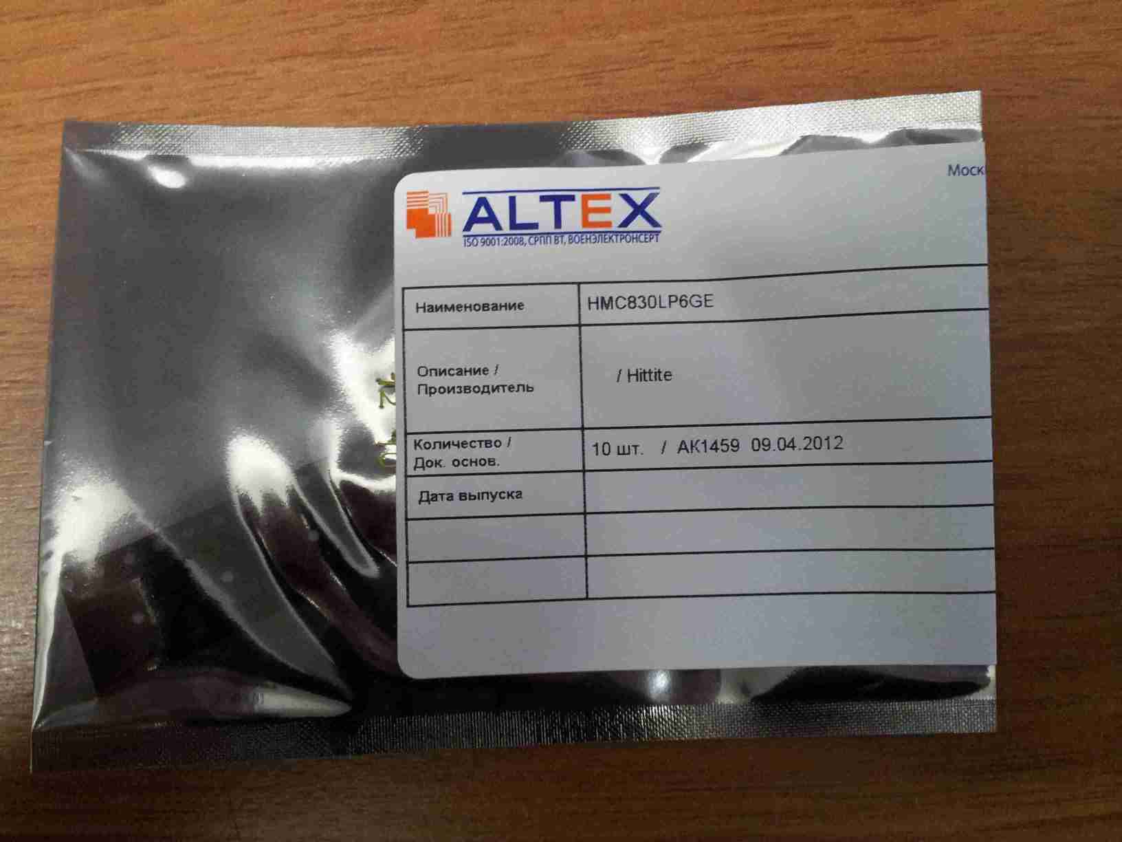
Hi Andrey. I'm back from vacation and will mail a package with 2 more Hittite HMC830LP6GE and 3 ADF4350BCPZ chips today and will e-mail the tracking number.
-Robin
2012/4/10 Andrey Sviyazov andreysviyaz@gmail.com:
Hi Robin!
I have a good news. I was received 10pcs samples of HMC830LP6GE, it was unexpectedly too fast. Sorry that I disturbed you about it.
Best regards, Andrey Sviyazov.
2 апреля 2012 г. 23:09 пользователь Andrey Sviyazov andreysviyaz@gmail.com написал:
Hi Robin. Thanks for the good news. When this happen, please send me by e-mail a copy of the postal receipt.
Best regards, Andrey Sviyazov. P.S. As I remember, you also offered few extra samples ADF4350, it would be absolutely great :)
2 апреля 2012 г. 19:44 пользователь Robin Coxe coxe@close-haul.com написал:
Hi Andrey. I got a notice that my Hittite rep has 2 samples. I'll try to connect them this week and will ship them to you as soon as I get them.
-Robin
2012/3/19 Andrey Sviyazov andreysviyaz@gmail.com:
Ok. Anyway, it will be much faster then request of samples from Moscow. Sorry regarding ADF4350 parameters, I mixed up it with ADF4360. What do you think about ADF4350 and HMC830 differences and usability?
Andrey.
20 марта 2012 г. 0:14 пользователь Robin Coxe coxe@close-haul.com написал:
OK, I'll send the chips directly to Andrey. The Hittite guy didn't say exactly when he'd have the samples. They usually insist on delivering them in person and it may take a week or so before he shows up.
2012/3/19 Andrey Sviyazov andreysviyaz@gmail.com
Ok, no problem. My home address:
Vilora Trifonova str., house 6, app. 45, Krasnogorsk сity, Moscow region, 143400, RUSSIA. Andrey Sviyazov. mobile: +7-916-828-7758.
19 марта 2012 г. 23:05 пользователь Alexander Chemeris alexander.chemeris@gmail.com написал:
> Andrey, > > 2012/3/19 Andrey Sviyazov andreysviyaz@gmail.com: > > Alexander, if you know faster way, let use it. > > Other hand, I need at least one week for RF-board design and 3-4 > > days > > for > > PCB production and delivery to my office. > > So, there are two weeks for EMS. > > DHL will be faster. But then it's better to ship to your address, as > I > will not be in Moscow the whole next week. Send you address to > Robin, > plz. > > -- > Regards, > Alexander Chemeris. > CEO, Fairwaves LLC / ООО УмРадио > http://fairwaves.ru
-- Robin Coxe | Close-Haul Communications, Inc. | Boston, MA +1-617-470-8825
-- Robin Coxe | Close-Haul Communications, Inc. | Boston, MA +1-617-470-8825
Hi Robin. I hope you had a nice vacation :)
Best regards, Andrey Sviyazov.
23 апреля 2012 г. 17:00 пользователь Robin Coxe coxe@close-haul.comнаписал:
Hi Andrey. I'm back from vacation and will mail a package with 2 more Hittite HMC830LP6GE and 3 ADF4350BCPZ chips today and will e-mail the tracking number.
-Robin
2012/4/10 Andrey Sviyazov andreysviyaz@gmail.com:
Hi Robin!
I have a good news. I was received 10pcs samples of HMC830LP6GE, it was unexpectedly too
fast.
Sorry that I disturbed you about it.
Best regards, Andrey Sviyazov.
2 апреля 2012 г. 23:09 пользователь Andrey Sviyazov <
andreysviyaz@gmail.com>
написал:
Hi Robin. Thanks for the good news. When this happen, please send me by e-mail a copy of the postal receipt.
Best regards, Andrey Sviyazov. P.S. As I remember, you also offered few extra samples ADF4350, it would be absolutely great :)
2 апреля 2012 г. 19:44 пользователь Robin Coxe coxe@close-haul.com написал:
Hi Andrey. I got a notice that my Hittite rep has 2 samples. I'll try to connect them this week and will ship them to you as soon as I get them.
-Robin
2012/3/19 Andrey Sviyazov andreysviyaz@gmail.com:
Ok. Anyway, it will be much faster then request of samples from
Moscow.
Sorry regarding ADF4350 parameters, I mixed up it with ADF4360. What do you think about ADF4350 and HMC830 differences and usability?
Andrey.
20 марта 2012 г. 0:14 пользователь Robin Coxe coxe@close-haul.com написал:
OK, I'll send the chips directly to Andrey. The Hittite guy didn't say exactly when he'd have the samples. They usually insist on
delivering
them in person and it may take a week or so before he shows up.
2012/3/19 Andrey Sviyazov andreysviyaz@gmail.com > > Ok, no problem. > My home address: > > Vilora Trifonova str., house 6, app. 45, Krasnogorsk сity, Moscow > region, > 143400, RUSSIA. > Andrey Sviyazov. > mobile: +7-916-828-7758. > > > > 19 марта 2012 г. 23:05 пользователь Alexander Chemeris > alexander.chemeris@gmail.com написал: > >> Andrey, >> >> 2012/3/19 Andrey Sviyazov andreysviyaz@gmail.com: >> > Alexander, if you know faster way, let use it. >> > Other hand, I need at least one week for RF-board design and 3-4 >> > days >> > for >> > PCB production and delivery to my office. >> > So, there are two weeks for EMS. >> >> DHL will be faster. But then it's better to ship to your address,
as
>> I >> will not be in Moscow the whole next week. Send you address to >> Robin, >> plz. >> >> -- >> Regards, >> Alexander Chemeris. >> CEO, Fairwaves LLC / ООО УмРадио >> http://fairwaves.ru > >
-- Robin Coxe | Close-Haul Communications, Inc. | Boston, MA +1-617-470-8825
-- Robin Coxe | Close-Haul Communications, Inc. | Boston, MA +1-617-470-8825
-- Robin Coxe | Close-Haul Communications, Inc. | Boston, MA +1-617-470-8825
Hi Andrey,
Thank you very much for your reply.
Thanks a lot for all the details you send. Yes, you are all right, Hittite mixers looks much more suitable than the ADL5801. These Hittite mixers have also a very high IIP3 and a resonable Noise Figure. Moreover, I agree with you, the ADL5801 integrated IF amp is not really suitable in our design.
Again, I agree with you. Receiving 2 carriers simultaneously on each Rx path will not be easy (LMS phase noise, ADC dynamic range, extra digital filtering...). We should keep just a single carrier per Rx path. This will allow to do switched diversity. This is already great.
Regarding the choice between HMC483MS8GE/HMC485MS8GE and HMC686LP4E/HMC687LP4E, I cannot figure out which one would be the most suitable for our design. For the filter, it is also quite difficult for me to help you to decide between the TB0130A and the TB0448A. By the way, do you think this would be fine to use a different mixer for 900 and 1800 MHz bands ? As chip packages remain the same, I think it would be fine but I would like to double check with you.
Regarding the GSM spec, I believe these blocker tests are hard to pass and not that useful in most practical situations. However, I do not care that much about passing this spec for my network deployment in Mayotte but I really believe passing the spec will be very important for you if you wish to sell your hardware solution to some major operators. Moreover, as we would anyway need a superheterodyne selective filtering to get a reasonably narrow Rx sampling band (< 1.5 MHz LMS band), it does not cost that much more to try to pass the GSM spec.
By the way, I really believe this does not worth designing 2 different preselectors. I think it would be more reasonable to design only the Hittite based high performance preselector. First of all, as you mentioned and as I calculate on my side also, the ADRF6601 will not even pass the micro BTS spec. Moreover, the time you spend designing and debugging 2 different preselector would probably cost more than the 40 USD per board you save on the boards you will use for low cost applications. Moreover, 2 different designs would mean lower quantities components order. This would mean higher buying prices, higher shipping costs per chip... In practice, the cost difference would be probably 25 to 30 USD per board, not 40 USD.
I really think we should only make one design with the Hittite high performance preselector. If we really want a low cost femtocell, a universal SDR board or a lab experiment system, we would not even populate the preselector components. If we need GSM deployment applications (except femtocells), nobody (even me ;-)) would actually care about the extra 40 USD BOM.
I looked at the picture of your Rx path calculations. As discussed together in Barcelona, I am not sure we should add an LNA on the UmTRX. TMB LNA would already have a very good Noise Figure (about 0.8 dB or even a bit less) and a quite high gain (between 20 to 30 dB depending of the cable loss). OIP3 of the TMB would be typacally around 35 dBm. Adding an extra on board LNA would be quite bad for the total Rx path IIP3. Moreover, as there is some PCB leakage from Tx to Rx in the UmTRX, we might avoid onboard amplifiers. An on board amplifier might actuallly amplify the leakage. I actually suggested this LNA a few months ago but, in Barcelona, you convinced me this LNA was not really a good idea. What do you think ?
Regarding the PA parameters, for both models we can get at a good price, P1dB would be between 8 (Infineon) to 15 (Freescale) Watts at 27 VDC (a bit lower at 24 VDC). Gain would be around 40 dB (excluding cable loss). Please let me know if you need others LNA and/or PA specs of the TMB I can get from the manufacturers I am discussing with.
Thank you very much for your great work on the design of the UmTRX. I really believe this will be a great board.
Best regards.
Jean-Samuel. :-)
2012/3/15 Andrey Sviyazov andreysviyaz@gmail.com
Hi Jean-Samuel!
About ADL5802, you can't use it as Down and Up converter simultaneously. Also I'm afraid that we can't yet receiving 2 GSM carriers simultaneously. So lets done single channel first but 2 or more keep in mind for experiments.
I try to find better components too. ADI mixers have internal IF AMP and it is not good in this case. Components of Hittite are known for me as a very good through my main job. I'd like to recommend to use any of the next: for GSM900 1/ HMC830LP6GE + HMC483MS8GE + TB0130A. (20.6+4.69+3=$28.29) 2/ HMC830LP6GE + HMC686LP4E + TB0448A. (20.6+9.67+3=$32.97) for DCS1800 1/ HMC830LP6GE + HMC485MS8GE + TB0130A . (20.6+4.69+3=$28.29) 2/ HMC830LP6GE + HMC687LP4E + TB0448A. (20.6+9.67+3=$32.97) By the way, LMS lower limit 0.3GHz as per datasheet.
About GSM 05.05 specs I still can't understand blocker requirements: MS spectrum with RBW=200kHz have -65dBc level at 600-1200kHz offset, therefore blocker MS with -26dBm will be jammer for wanted MS with level less then -91dBm and noise level of receiver's heterodyne isn't matter in this case. I really can't understand why CW levels -26dBm and -16dBm blocking tests required. May be it just universal test of heterodyne quality?
I think we should be reasonable people, and therefore we should use parameters which really necessary for us. So, ADRF6601 parameters seems to be quite enough even if it pass only mBS requirements. On the other hand, BOM difference between ADRF and HMC's around $20-25 only and it isn't much for normal BS. In short, it seems that we should do three options front-end mezzanines: 1/ without channel preselector for picoBS or nanoBS upto 0.5W/ch. 2/ preselector ADRF based for microBS upto 2W/ch. 3/ preselector HMC based for normal BS with 10-20W/ch TMB.
Please find attached pictures that my simple calculations for RX chain. Also, please let me know real PA parameters which you decide to use for TMB.
Best regards, Andrey Sviyazov.
15 марта 2012 г. 4:42 пользователь Jean-Samuel Najnudel - BJT PARTNERS SARL jsn@bjtpartners.com написал:
Hi Andrey,
Thank you for your e-mail.
Yes, you are all right.
It think your calculations are good. I just did not knew how hard was the GSM macro BTS spec.
I browsed a bit the web and found the GSM 05.05 specs which confirm what you say. I also found some similar information and calculations in an academic paper which confirm your figures. http://www.uta.edu/rfmems/Conferences/2001_SPIE_MicroMEMS/4592-20.pdf(page 5 and 6)
Anyway, I tried to look at other components than the ADRF6601.
I found a quite low phase noise VCO/PLL from Hittite which seems to be able to let us probably pass the macro BTS spec or at least the micro BTS spec. http://www.hittite.com/products/view.html/view/HMC830LP6GE
For the mixer, we may use a separate component like the ADL5801.
Please let me know what you think about these chips. Please do not hesitate to let us know some other suggestions if you know or if you can find some other components that would have better performances.
Actually, even if the specs are not easy to pass, I still feel quite optimistic as it was possible to pass these specs 15 years old components. Anyway, if the macro BTS specs are really too hard to pass, we may focus on the micro BTS spec. This would already be great to convince the market you may be interested in and the performances would be good enough for most practical situations in my deployment in Mayotte.
Best regards.
Jean-Samuel. :-)
2012/3/14 Andrey Sviyazov andreysviyaz@gmail.com
Hi all!
I am again about far-near problem.
If we have heterodyne noise -135dBc/Hz at 600kHz offset (ADRF6601), then for blocking signal at the same offset and at 200kHz RBW we get additional noise level 135-53=72dBc relative to blocking signal level. To keep "normal GSM900 BS" sensitivity -104dBm we must keep additional noise as low as -107dBm, therefore blocking signal maximum level must less then -107+73=-39dBm. But in GSM-05.05 (sec 5.1) I saw blocking characteristics requirements for normal BTS must be -26 dBm at 0.6-0.8 MHz offset and -16 dBm at 0.8-1.6 MHz offset. So, I do not know how and who can meet those requirements and I am really hope that there are fundamental mistakes in my calculations. Correct me please.
Best regards, Andrey Sviyazov.
16 января 2012 г. 19:22 пользователь Jean-Samuel Najnudel - BJT PARTNERS SARL jsn@bjtpartners.com написал:
Hi Alexander,
These last days, I tried to find a solution for the selectivity improvement.
I have 5 solutions to propose. 1st and 2nd are inboard solutions. 3rd, 4th and 5th uses an external board. Some seems to be much better than others.
1/ We could use an IF frequency above 375 MHz to be able to connect the IF signal dirtectly to the LMS, without any upconvertion back to RF frequency. This would save some components. We could use the ADRF6601 (PLL/VCO + mixer) and the TB0448A IF SAW filter. The ADRF6601 is single chip PLL/VCO and mixer. This would be quite convenient. The TB0448A is cheap (< 3 USD), narrow band (good selectivity) and 400 MHz center frequency (> 375 MHz LMS lower limit).
Cost of this solution would be about 60 USD and selectivity would be really good. The main disadvantage of this solution is the filter would restrict the signal to a single GSM carrier. This would avoid us to get both GSM carriers on each LMS. We would not be able to get true diversity. We would only be able to get switched diversity.
After the LNA, RF SAW filter and the RF switches, we can split the signal between the current RX path to LMS RX LNA 3 and a new alternate RX path (ADRF6601 => TB0448A => LMS RX LNA 1). Depending of our need for selectivity, we would be able to select 1 of these 2 RX path (direct RX path to LMS RX LNA 3 or IF filter RX path to LMS RX LNA1).
This would allow to use the board either as a normal wideband SDR board or with a very selective filter.
2/ A very nice option would be to use a variant of the 1st solution with a wider bandwidth SAW IF filter. For example, if we use a 400 to 600 KHz bandwidth IF filter, we would also get a very good selectivity and we would also be able to sample both GSM carriers on each LMS. This would allow a good selectivity and full diversity.
The problem is we would need a 400 to 600 KHz SAW IF filter, with good selectivity, reasonable price and an IF center frequency above 375 MHz. I was not able to find such a filter.
3/ As suggested a few days ago, we may use the external selectivity improvement board design I sent you. Instead of the Triquint 856378 IF SAW filter, we could use the TAISAW TB0448A narrow band filter. This TAISAW filter is really much cheaper than the Triquint. This would save a lot of budget. However, we would still need 4 mixer and 2 PLL/VCO for each LMS RX path. This external board would cost approximately 100 USD (excluding PCB and assembly). We would need 2 of these boards for each UmTRX board. This would make 200 USD per UmTRX. Including PCB and assembly, toatl cost would be around 300 USD. This is not compeltely unrealistic but it seems still quite expensive.
4/ Another solution would be to build a single carrier version of the 3rd solution design. We would need only 1 RF path (PLL/VCO + mixer) with only 1 narrow band filter per LMS RX path. This would not need any splitter or combiner. Design would be quite simple and cost would be about 2 times lower. However, as we will have only 1 carrier on each antenna, we would not be able to get diversity at all.
This solution would finally not have many advantages compared to 1st solution. It would cost more and would not allow any kind of diversity.
5/ Last solution would be to build an external diversity improvement board, as 4th solution, but with a wider band IF SAW filter.
We could use the following RF path: LNA => RF SAW filter => mixer => IF SAW filter => mixer => RF SAW filter. Dual mixer could be the ADL5802 connected to the ADF4350 PLL/VCO.
We could use the TB0218A IF SAW filter. This filter is quite affordable (< 10 USD). Selectivity is good and bandwidth is wide enough to select 2 GSM carriers (separated by 400 KHz).
Cost of such external diversity improvement board would be quite reasonable. This would be a very nice solution to select 2 GSM carriers. Connected to the UmTRX, this selectivity improvement board would allow to get both switched or true diversity.
As TB0218A center frequency is 140 MHz, we would not be able to connect directly the IF signal to the LMS. We would need to up convert the signal back to the RF frequency. As IF down converted signal is upconverted back to the original RF frequency, it would be possible to use this selectivity improvement board with any kind of existing OpenBTS (UmTRX, USRP, SSRP...) or OpenBSC (Sysmocom BTS, IP.access nanoBTS...) hardware to improve the Rx selectivity. This would offer a wider potential market than an inboard solution.
Considering all these solution, I believe 1st and 5th solutions seems to be the best choices. 2nd solution would also be really nice but I was not able to find the appropriate IF SAW filter. Please let me know your opinion regarding each of these two solutions.
By the way, the TB0448A and TB0218A SAW filters looks really good but I am not 100% sure the GSM carrier spectrum distortion due to the pass band ripple of the SAW filter is acceptable. Center part of the GSM carrier (f +/- 100 KHz) is fine but side parts of the GSM carrier (bellow f - 100 KHz and above f + 100 KHz) may be cut a bit by the SAW filter.
Could you also please check the TB0448A and TB0218A datasheets to double check if the usable bandwidth is wide enough ? Especially, do you think cutting a bit the side parts of the GSM carrier may cause problem ?
Anyway, please let me know your point of view regarding these selectivity improvement solutions.
Best regards.
Jean-Samuel. :-)
Hi Jean-Samuel!
Some answers and reasons below.
Regarding the choice between HMC483MS8GE/HMC485MS8GE and
HMC686LP4E/HMC687LP4E, I cannot figure out which one would be the most suitable for our design. For the filter, it is also quite difficult for me to help you to decide between the TB0130A and the TB0448A.
By the way, do you think this would be fine to use a different mixer for
900 and 1800 MHz bands ? As chip packages remain the same, I think it would be fine but I would like to double check with you.
Differences between HMC 483/483 and HMC686/687: 1/ price of HMC483/485 twice lower. 2/ current consumption of HMC483/485 twice lower. 3/ package ms8g better for me. 4/ I have good expirience with HMC483/485 and some qty there are on my warehouse in Moscow. 5/ HMC483/485 require TB0130A which have 20dB higher rejection than TB448A. So, HMC483/485 better for me.
Regarding the GSM spec, I believe these blocker tests are hard to pass and
not that useful in most practical situations. However, I do not care that much about passing this spec for my network deployment in Mayotte but I really believe passing the spec will be very important for you if you wish to sell your hardware solution to some major operators. Moreover, as we would anyway need a superheterodyne selective filtering to get a reasonably narrow Rx sampling band (< 1.5 MHz LMS band), it does not cost that much more to try to pass the GSM spec.
You right, it is important for us and may be it is really important for systems with high channel dencity. Furthermore, it is very easy to lose the reputation of the product, but it is very difficult then to fix it back. I think, low cost doesn't sign low quality, so we must to have good hardware on market for good sales and promote OpenHW :)
By the way, I really believe this does not worth designing 2 different preselectors. I think it would be more reasonable to design only the Hittite based high performance preselector. First of all, as you mentioned and as I calculate on my side also, the ADRF6601 will not even pass the micro BTS spec. Moreover, the time you spend designing and debugging 2 different preselector would probably cost more than the 40 USD per board you save on the boards you will use for low cost applications. Moreover, 2 different designs would mean lower quantities components order. This would mean higher buying prices, higher shipping costs per chip... In practice, the cost difference would be probably 25 to 30 USD per board, not 40 USD.
I really think we should only make one design with the Hittite high performance preselector. If we really want a low cost femtocell, a universal SDR board or a lab experiment system, we would not even populate the preselector components. If we need GSM deployment applications (except femtocells), nobody (even me ;-)) would actually care about the extra 40 USD BOM.
Exactly, I agree again.
I looked at the picture of your Rx path calculations. As discussed together in Barcelona, I am not sure we should add an LNA on the UmTRX. TMB LNA would already have a very good Noise Figure (about 0.8 dB or even a bit less) and a quite high gain (between 20 to 30 dB depending of the cable loss). OIP3 of the TMB would be typacally around 35 dBm. Adding an extra on board LNA would be quite bad for the total Rx path IIP3.
How you define that 35 dBm OIP3 required? I saw only -1dBm IIP3 in the datasheet for middle Gain of LNA2 and it isn't informative for me.
Moreover, as there is some PCB leakage from Tx to Rx in the UmTRX, we might avoid onboard amplifiers. An on board amplifier might actuallly amplify the leakage. I actually suggested this LNA a few months ago but, in Barcelona, you convinced me this LNA was not really a good idea. What do you think ?
Duplexer+PA(0.25..2W)+LNA+Preselector are all will be on the mezzanine board for uBTS, nBTS and mBTS solutions TMD. So, you right - new UmTRX will be without LNA's and bandpass filters, because it is universal dual tranceiver with diversity switch. As we discussed in Barcelona, we forced to design different mezza-boards for each band, but it much easy than UmTRX changes. Also high power "mezza-boards" will be not as true mezzanine because of require heatsink and separate power source.
Regarding the PA parameters, for both models we can get at a good price,
P1dB would be between 8 (Infineon) to 15 (Freescale) Watts at 27 VDC (a bit lower at 24 VDC). Gain would be around 40 dB (excluding cable loss). Please let me know if you need others LNA and/or PA specs of the TMB I can get from the manufacturers I am discussing with.
Actualy I really thought that you already have offers about PA or TMB from Chinese manufactures.
Best regards, Andrey Sviyazov.
Hi Andrey,
Thank you very much for these answers. Please see my comments bellow.
On Sat, Mar 17, 2012 at 11:31 PM, Andrey Sviyazov andreysviyaz@gmail.comwrote:
Hi Jean-Samuel!
Some answers and reasons below.
Regarding the choice between HMC483MS8GE/HMC485MS8GE and
HMC686LP4E/HMC687LP4E, I cannot figure out which one would be the most suitable for our design. For the filter, it is also quite difficult for me to help you to decide between the TB0130A and the TB0448A.
By the way, do you think this would be fine to use a different mixer for
900 and 1800 MHz bands ? As chip packages remain the same, I think it would be fine but I would like to double check with you.
Differences between HMC 483/483 and HMC686/687: 1/ price of HMC483/485 twice lower. 2/ current consumption of HMC483/485 twice lower. 3/ package ms8g better for me. 4/ I have good expirience with HMC483/485 and some qty there are on my warehouse in Moscow. 5/ HMC483/485 require TB0130A which have 20dB higher rejection than TB448A. So, HMC483/485 better for me.
This looks fine for me. However, I cannot see 20 dB higher rejection for TB0130A, may be 5 or 10 dB, not more. Anyway, this is still better. Just to double check, could you please confirm low ripple bandwidth of the TB0130A is wide enough for a GSM carrier ? If yes, your choice looks perfect for me.
Regarding the GSM spec, I believe these blocker tests are hard to pass and
not that useful in most practical situations. However, I do not care that much about passing this spec for my network deployment in Mayotte but I really believe passing the spec will be very important for you if you wish to sell your hardware solution to some major operators. Moreover, as we would anyway need a superheterodyne selective filtering to get a reasonably narrow Rx sampling band (< 1.5 MHz LMS band), it does not cost that much more to try to pass the GSM spec.
You right, it is important for us and may be it is really important for systems with high channel dencity. Furthermore, it is very easy to lose the reputation of the product, but it is very difficult then to fix it back. I think, low cost doesn't sign low quality, so we must to have good hardware on market for good sales and promote OpenHW :)
I agree. :-)
By the way, I really believe this does not worth designing 2 different preselectors. I think it would be more reasonable to design only the Hittite based high performance preselector. First of all, as you mentioned and as I calculate on my side also, the ADRF6601 will not even pass the micro BTS spec. Moreover, the time you spend designing and debugging 2 different preselector would probably cost more than the 40 USD per board you save on the boards you will use for low cost applications. Moreover, 2 different designs would mean lower quantities components order. This would mean higher buying prices, higher shipping costs per chip... In practice, the cost difference would be probably 25 to 30 USD per board, not 40 USD.
I really think we should only make one design with the Hittite high performance preselector. If we really want a low cost femtocell, a universal SDR board or a lab experiment system, we would not even populate the preselector components. If we need GSM deployment applications (except femtocells), nobody (even me ;-)) would actually care about the extra 40 USD BOM.
Exactly, I agree again.
:-)
I looked at the picture of your Rx path calculations. As discussed together in Barcelona, I am not sure we should add an LNA on the UmTRX. TMB LNA would already have a very good Noise Figure (about 0.8 dB or even a bit less) and a quite high gain (between 20 to 30 dB depending of the cable loss). OIP3 of the TMB would be typacally around 35 dBm. Adding an extra on board LNA would be quite bad for the total Rx path IIP3.
How you define that 35 dBm OIP3 required? I saw only -1dBm IIP3 in the datasheet for middle Gain of LNA2 and it isn't informative for me.
35 dBm OIP3 is not really required. I would say, the highest is the best as long as price is reasonable. High OIP3 would avoid IMD interferences problems. I already have some offers, products and prototypes from Chinese manufacturers. The OIP3 of the LNA they can provide is around 35 dBm.
Moreover, as there is some PCB leakage from Tx to Rx in the UmTRX, we might avoid onboard amplifiers. An on board amplifier might actuallly amplify the leakage. I actually suggested this LNA a few months ago but, in Barcelona, you convinced me this LNA was not really a good idea. What do you think ?
Duplexer+PA(0.25..2W)+LNA+Preselector are all will be on the mezzanine board for uBTS, nBTS and mBTS solutions TMD. So, you right - new UmTRX will be without LNA's and bandpass filters, because it is universal dual tranceiver with diversity switch. As we discussed in Barcelona, we forced to design different mezza-boards for each band, but it much easy than UmTRX changes. Also high power "mezza-boards" will be not as true mezzanine because of require heatsink and separate power source.
I agree for band specific filters (to avoid too many UmTRX versions). I agree for LNA (to avoid amplifying the Tx leakage inside the UmTRX PCB and to avoid a too high gain that can lower our IIP3). I agree for the PA (for all the reasons you mention).
However, I really believe the preselector should remain on the UmTRX main PCB. If we want to connect the preselector as an external mezzanine board, it would cost us 5 extra SMA connectors (RX1in, RX1out, RX2in, RX2out, clock source), 2 RF switches before the superhet filtering (to still be able to have switched diversity), several GPIO (serial mixer control, RF switches control) and power supply. This is possible but it would really cost much more than keeping the preselector on the main PCB, especially as I believe, in practice, we will need almsot always this preselector, even not to pass the GSM spec but just to be able to get a reasonably narrow sampling bandwidth. I would really suggest to keep the preselector in the main PCB and populating or not the components (VCO/PLL, mixer and SAW IF).
Regarding the PA parameters, for both models we can get at a good price,
P1dB would be between 8 (Infineon) to 15 (Freescale) Watts at 27 VDC (a bit lower at 24 VDC). Gain would be around 40 dB (excluding cable loss). Please let me know if you need others LNA and/or PA specs of the TMB I can get from the manufacturers I am discussing with.
Actualy I really thought that you already have offers about PA or TMB from Chinese manufactures.
Yes, I have some interesting offers. I am still discussing with them but they propose nice products for affordable prices.
Best regards, Andrey Sviyazov.
Best regards.
Jean-Samuel. :-)
Hi Jean-Samuel and Andrey,
On Sun, Mar 18, 2012 at 18:25, Jean-Samuel Najnudel - BJT PARTNERS SARL jsn@bjtpartners.com wrote:
However, I really believe the preselector should remain on the UmTRX main PCB. If we want to connect the preselector as an external mezzanine board, it would cost us 5 extra SMA connectors (RX1in, RX1out, RX2in, RX2out, clock source), 2 RF switches before the superhet filtering (to still be able to have switched diversity), several GPIO (serial mixer control, RF switches control) and power supply. This is possible but it would really cost much more than keeping the preselector on the main PCB, especially as I believe, in practice, we will need almsot always this preselector, even not to pass the GSM spec but just to be able to get a reasonably narrow sampling bandwidth. I would really suggest to keep the preselector in the main PCB and populating or not the components (VCO/PLL, mixer and SAW IF).
Could we save on connectors if we use some RF side connector with many pins? Nothing specific in mind, just thinking out loud.
Hi Andrey,
What do you think about Alexander's suggestion ? If we can find an affordable and convenient solution to connect to the mezzanine board on the UmTRX, this would be great. It would allow us to start the production of the first release of the UmTRX while we work on the mezzanine board design. If we do not have any other solution than using standard SMA connectors, it would cost us quite a lot (connectors, balun, matching...) and it might be a better solution to have the preselecter on the UmTRX PCB. What do you think ? :-)
On Sun, Mar 18, 2012 at 6:13 PM, Alexander Chemeris < alexander.chemeris@gmail.com> wrote:
Hi Jean-Samuel and Andrey,
On Sun, Mar 18, 2012 at 18:25, Jean-Samuel Najnudel - BJT PARTNERS SARL jsn@bjtpartners.com wrote:
However, I really believe the preselector should remain on the UmTRX main PCB. If we want to connect the preselector as an external mezzanine board, it would cost us 5 extra SMA connectors (RX1in, RX1out, RX2in, RX2out, clock source), 2 RF switches before the superhet filtering (to still be able to have switched diversity), several GPIO (serial mixer control, RF switches control) and power supply. This is possible but it would really cost much more than keeping the preselector on the main PCB, especially as I believe, in practice, we
will
need almsot always this preselector, even not to pass the GSM spec but
just
to be able to get a reasonably narrow sampling bandwidth. I would really suggest to keep the preselector in the main PCB and populating or not the components (VCO/PLL, mixer and SAW IF).
Could we save on connectors if we use some RF side connector with many pins? Nothing specific in mind, just thinking out loud.
-- Regards, Alexander Chemeris. CEO, Fairwaves LLC / ООО УмРадио http://fairwaves.ru
Hi Jean-Samuel, Robin, Alexander and who interested too!
First of all, we discussing here not an mezzanine, so let we call it just RF-board.
I still intend to make a separate RF-board on the following reasons: 1) Minimises of risk of a delay of the new UmTRX issue if I make some mistake, especially if this will not fixable after manufacture. Redesign of RF-board much easily and quickly in this a bit possible case. 2) As it is rightly said Jean-Samuel, different boards of UmTRX for each band would be very expensive and long to redesign. I think that the design of a separate RF-board will take no more than two weeks, but for UmTRX not less than month, because I'll forced to make the screening from the digital part, and then checking the immunity against the digital noise and it is a very difficult task. 3) I plan to use for RF-board an simple and cheapest dual-layer FR-4-0.5mm and this will reduce the cost too, because of main UmTRX has six-layers PCB and I will try to make the new UmTRX optimaly smallest. 4) On the RF-board, I plan to use inexpensive ceramic duplexers to save the cost of the external (see attached datasheet). As I undersand, you do not need any Down Link PA or some small (up to 100mW), so Tx-Rx isolation will quite enough. 5) Regarding connectors, I only can suggest to use the two angle SMA-female connectors for outputs which will stick out through the panel of the housing (as you can use the angle SMA connectors, but for GPS and CLK_I/O on the UmTRX board). At the same time for the internal 4 connectors we can use some cheap like U.FL and cable assemblies U.FL-MCX or U.FL-U.FL. Signal CLK_26MHz, 6.5VDC, SPI and Switch controls will go via IDC control connector.
Best regards, Andrey Sviyazov.
18 марта 2012 г. 21:23 пользователь Jean-Samuel Najnudel - BJT PARTNERS SARL jsn@bjtpartners.com написал:
Hi Andrey,
What do you think about Alexander's suggestion ? If we can find an affordable and convenient solution to connect to the mezzanine board on the UmTRX, this would be great. It would allow us to start the production of the first release of the UmTRX while we work on the mezzanine board design. If we do not have any other solution than using standard SMA connectors, it would cost us quite a lot (connectors, balun, matching...) and it might be a better solution to have the preselecter on the UmTRX PCB.
What do you think ? :-)
On Sun, Mar 18, 2012 at 6:13 PM, Alexander Chemeris < alexander.chemeris@gmail.com> wrote:
Hi Jean-Samuel and Andrey,
On Sun, Mar 18, 2012 at 18:25, Jean-Samuel Najnudel - BJT PARTNERS SARL jsn@bjtpartners.com wrote:
However, I really believe the preselector should remain on the UmTRX
main
PCB. If we want to connect the preselector as an external mezzanine board, it would cost us 5 extra SMA connectors (RX1in, RX1out, RX2in, RX2out,
clock
source), 2 RF switches before the superhet filtering (to still be able
to
have switched diversity), several GPIO (serial mixer control, RF
switches
control) and power supply. This is possible but it would really cost much more than keeping the preselector on the main PCB, especially as I believe, in practice, we
will
need almsot always this preselector, even not to pass the GSM spec but
just
to be able to get a reasonably narrow sampling bandwidth. I would really suggest to keep the preselector in the main PCB and populating or not the components (VCO/PLL, mixer and SAW IF).
Could we save on connectors if we use some RF side connector with many pins? Nothing specific in mind, just thinking out loud.
-- Regards, Alexander Chemeris. CEO, Fairwaves LLC / ООО УмРадио http://fairwaves.ru
Andrey,
2012/3/19 Andrey Sviyazov andreysviyaz@gmail.com:
- Regarding connectors, I only can suggest to use the two angle SMA-female
connectors for outputs which will stick out through the panel of the housing (as you can use the angle SMA connectors, but for GPS and CLK_I/O on the UmTRX board). At the same time for the internal 4 connectors we can use some cheap like U.FL and cable assemblies U.FL-MCX or U.FL-U.FL. Signal CLK_26MHz, 6.5VDC, SPI and Switch controls will go via IDC control connector.
IDC connectors on a UmTRX and on a RF board will be connected with a flat ribbon cable?
Why don't you want to use a side connector?
Hi Alexander.
Actualy I don't know side-type connectors for cable. I suggested you PCB side connector (like PCI) for debugging only. Moreover, there are a lot SMD connectors for IDC flat cable, BHS-10 for example.
Best regards, Andrey Sviyazov.
19 марта 2012 г. 10:14 пользователь Alexander Chemeris < alexander.chemeris@gmail.com> написал:
Andrey,
2012/3/19 Andrey Sviyazov andreysviyaz@gmail.com:
- Regarding connectors, I only can suggest to use the two angle
SMA-female
connectors for outputs which will stick out through the panel of the
housing
(as you can use the angle SMA connectors, but for GPS and CLK_I/O on the UmTRX board). At the same time for the internal 4 connectors we can use
some
cheap like U.FL and cable assemblies U.FL-MCX or U.FL-U.FL. Signal CLK_26MHz, 6.5VDC, SPI and Switch controls will go via IDC control connector.
IDC connectors on a UmTRX and on a RF board will be connected with a flat ribbon cable?
Why don't you want to use a side connector?
-- Regards, Alexander Chemeris. CEO, Fairwaves LLC / ООО УмРадио http://fairwaves.ru
Andrey,
What I proposed is to use a side connector to connect UmTRX PCB and RF board OCB side-to-side, without a cable. This way we need two connectors and no cables at all. Downside of this solution is less flexibility in the RF board placement, but do we really need this flexibility?
2012/3/19 Andrey Sviyazov andreysviyaz@gmail.com:
Hi Alexander.
Actualy I don't know side-type connectors for cable. I suggested you PCB side connector (like PCI) for debugging only. Moreover, there are a lot SMD connectors for IDC flat cable, BHS-10 for example.
Best regards, Andrey Sviyazov.
19 марта 2012 г. 10:14 пользователь Alexander Chemeris alexander.chemeris@gmail.com написал:
Andrey,
2012/3/19 Andrey Sviyazov andreysviyaz@gmail.com:
- Regarding connectors, I only can suggest to use the two angle
SMA-female connectors for outputs which will stick out through the panel of the housing (as you can use the angle SMA connectors, but for GPS and CLK_I/O on the UmTRX board). At the same time for the internal 4 connectors we can use some cheap like U.FL and cable assemblies U.FL-MCX or U.FL-U.FL. Signal CLK_26MHz, 6.5VDC, SPI and Switch controls will go via IDC control connector.
IDC connectors on a UmTRX and on a RF board will be connected with a flat ribbon cable?
Why don't you want to use a side connector?
-- Regards, Alexander Chemeris. CEO, Fairwaves LLC / ООО УмРадио http://fairwaves.ru
Hi all!
First of all, I forgot one question regarding the IF SAW filters. TB0130A has at least 10dB higher rejection at 0.6-0.9MHz offset band (65dB) than TB448A (55dB), and 20dB higher rejection at 0.9-1.5MHz offset band (75dB instead of 55dB). Moreover, TB0130A has more flatter and wider passband, approx 300kHz at 0.5dB instead of 250kHz for TB448A, it is better because of this type SAW has thermal drift approx +-32 kHz for +-50'C relative to +25'C. In other hand, TB448A has better group delay ripples, but I don't how it critical for GMSK, and I'm sure that symmetry law more important. Also we can adjust central IF for 3-5 temperature points, but in this case we need to add thermal measurements, and let we try to avoid it.
Best regards, Andrey Sviyazov.
19 марта 2012 г. 12:30 пользователь Andrey Sviyazov andreysviyaz@gmail.comнаписал:
Hi Alexander.
Actualy I don't know side-type connectors for cable. I suggested you PCB side connector (like PCI) for debugging only. Moreover, there are a lot SMD connectors for IDC flat cable, BHS-10 for example.
Best regards, Andrey Sviyazov.
19 марта 2012 г. 10:14 пользователь Alexander Chemeris < alexander.chemeris@gmail.com> написал:
Andrey,
2012/3/19 Andrey Sviyazov andreysviyaz@gmail.com:
- Regarding connectors, I only can suggest to use the two angle
SMA-female
connectors for outputs which will stick out through the panel of the
housing
(as you can use the angle SMA connectors, but for GPS and CLK_I/O on the UmTRX board). At the same time for the internal 4 connectors we can use
some
cheap like U.FL and cable assemblies U.FL-MCX or U.FL-U.FL. Signal CLK_26MHz, 6.5VDC, SPI and Switch controls will go via IDC control connector.
IDC connectors on a UmTRX and on a RF board will be connected with a flat ribbon cable?
Why don't you want to use a side connector?
-- Regards, Alexander Chemeris. CEO, Fairwaves LLC / ООО УмРадио http://fairwaves.ru
-
 Alexander Chemeris
 -
 Andrey Sviyazov
 -
 Jean-Samuel Najnudel - BJT PARTNERS SARL
 -
 Robin Coxe