
Sorry, that was meant to be sent to the mailing list :)
Best regards, Andrey Sviyazov.
---------- Forwarded message ---------- From: Andrey Sviyazov andreysviyaz@gmail.com Date: 2012/7/18 Subject: LMS TxLO noise
Hi Thomas.
Here forwarded my last e-mail with noise plots when I stopped work around it at first time, please see below.
Please try to play around Tx PLL charge pump current (register 0x16) for better RMS phase stability. I think we should reach 1 degree or below.
Alexander gave me the second UmTRX board and after checking and fixing all known hardware issueshttp://code.google.com/p/umtrx/issues/list?can=1&q=&colspec=ID+Type+Status+Priority+Milestone+Owner+Summary+Modified&cells=tilesI've got roughly the same LO noise plot. Possible Robin had no time to fixing all of our issues, so check them all please. And also check please what type of TCXO installed on your board.
Best regards, Andrey Sviyazov.
---------- Forwarded message ---------- From: Andrey Sviyazov andreysviyaz@gmail.com Date: 2012/4/13 Subject: Re: LMS TxLO noise
Hi all.
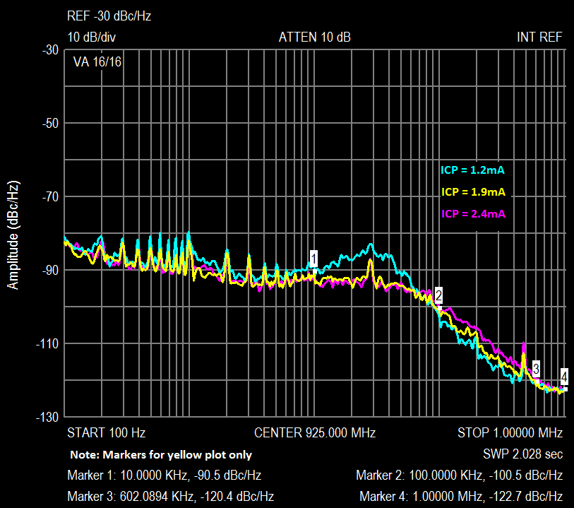
There is progress with LMS PLL :) Pictures are attached here. t was discovered that 80 kHz spurs come from Ethernet, or rather from the ET1011. I unknowingly put the choke between transistor of 1V regulator and analog power 1V. As a result, the regulator has become unstable and oscillated 80 kHz with amplitude of 200 mV, which climbed into the LMS PLL. To correct this problem L46 should be replaced by jumper on all alfa version PCB's.
Also I just played with current in the PLL loop, shown on the picture for clarity. Proved to be the optimal current 1,9 mA (you should write 0x93 in the register of 0x16). But, I think, for the RxPLL will be better use of the current 2.4 mA, because the nearest noises more important for Rx (you should write 0x98 in the register 0x26).
Best regards, Andrey Sviyazov.
Hi all.
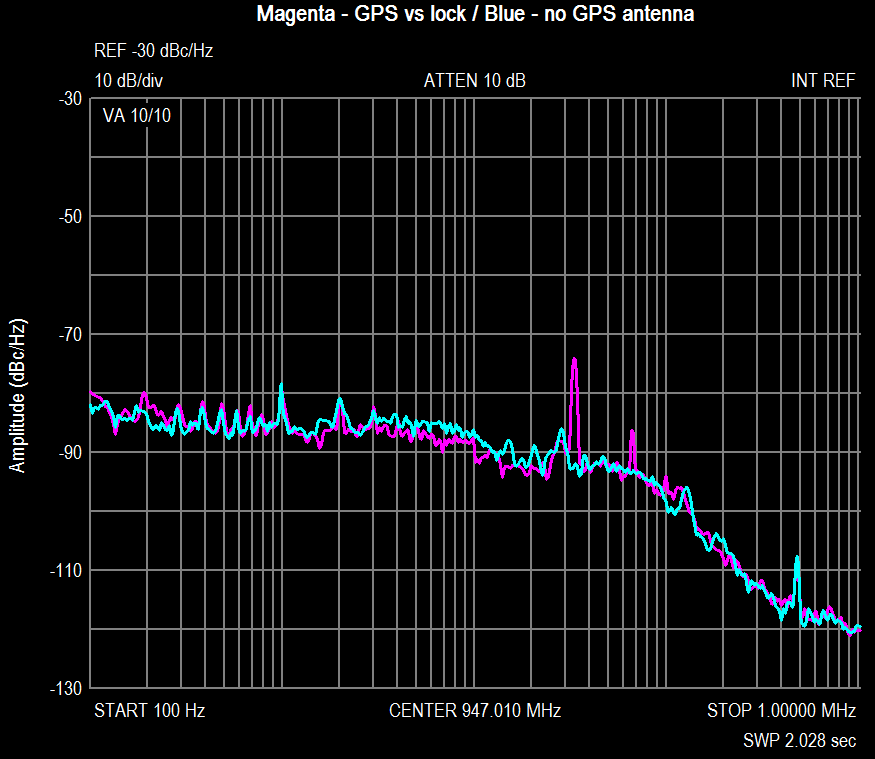
I've found spurs on the LO noise plot at ~33kHz and ~66kHz offset when GPS antenna used and position locked. This spurs begin grow up when GPS just near to lock position and after locking spurs stopped to grow as you can see at picture. If thereafter GPS disconnected then noise coming back to normal plot. I think that it is result of 32768Hz clock in the GPS module EB-230, but can't understant how it can impact to 26MHz clock or VCO. Please tell me something who know.
Thomas. Was GPS antenna connected when noise measured like on the picture which you sent us (also attached here)? I would to know because of anomal peak near to 30kHz offset too.
Best regards, Andrey Sviyazov.
2012/7/19 Andrey Sviyazov andrey.sviyazov@fairwaves.ru
Sorry, that was meant to be sent to the mailing list :)
Best regards, Andrey Sviyazov.
---------- Forwarded message ---------- From: Andrey Sviyazov andreysviyaz@gmail.com Date: 2012/7/18 Subject: LMS TxLO noise
Hi Thomas.
Here forwarded my last e-mail with noise plots when I stopped work around it at first time, please see below.
Please try to play around Tx PLL charge pump current (register 0x16) for better RMS phase stability. I think we should reach 1 degree or below.
Alexander gave me the second UmTRX board and after checking and fixing all known hardware issueshttp://code.google.com/p/umtrx/issues/list?can=1&q=&colspec=ID+Type+Status+Priority+Milestone+Owner+Summary+Modified&cells=tilesI've got roughly the same LO noise plot. Possible Robin had no time to fixing all of our issues, so check them all please. And also check please what type of TCXO installed on your board.
Best regards, Andrey Sviyazov.
---------- Forwarded message ---------- From: Andrey Sviyazov andreysviyaz@gmail.com Date: 2012/4/13 Subject: Re: LMS TxLO noise
Hi all.
There is progress with LMS PLL :) Pictures are attached here. t was discovered that 80 kHz spurs come from Ethernet, or rather from the ET1011. I unknowingly put the choke between transistor of 1V regulator and analog power 1V. As a result, the regulator has become unstable and oscillated 80 kHz with amplitude of 200 mV, which climbed into the LMS PLL. To correct this problem L46 should be replaced by jumper on all alfa version PCB's.
Also I just played with current in the PLL loop, shown on the picture for clarity. Proved to be the optimal current 1,9 mA (you should write 0x93 in the register of 0x16). But, I think, for the RxPLL will be better use of the current 2.4 mA, because the nearest noises more important for Rx (you should write 0x98 in the register 0x26).
Best regards, Andrey Sviyazov.

On Thu, Jul 19, 2012 at 6:10 PM, Andrey Sviyazov < andrey.sviyazov@fairwaves.ru> wrote:
Hi all.
I've found spurs on the LO noise plot at ~33kHz and ~66kHz offset when GPS antenna used and position locked. This spurs begin grow up when GPS just near to lock position and after locking spurs stopped to grow as you can see at picture. If thereafter GPS disconnected then noise coming back to normal plot. I think that it is result of 32768Hz clock in the GPS module EB-230, but can't understant how it can impact to 26MHz clock or VCO.
As another idea it can be caused by continues GPS correction lead to DAC changes to the VCTXCO.
Please tell me something who know.
Thomas. Was GPS antenna connected when noise measured like on the picture which you sent us (also attached here)? I would to know because of anomal peak near to 30kHz offset too.
Best regards, Andrey Sviyazov.
2012/7/19 Andrey Sviyazov andrey.sviyazov@fairwaves.ru
Sorry, that was meant to be sent to the mailing list :)
Best regards, Andrey Sviyazov.
---------- Forwarded message ---------- From: Andrey Sviyazov andreysviyaz@gmail.com Date: 2012/7/18 Subject: LMS TxLO noise
Hi Thomas.
Here forwarded my last e-mail with noise plots when I stopped work around it at first time, please see below.
Please try to play around Tx PLL charge pump current (register 0x16) for better RMS phase stability. I think we should reach 1 degree or below.
Alexander gave me the second UmTRX board and after checking and fixing all known hardware issueshttp://code.google.com/p/umtrx/issues/list?can=1&q=&colspec=ID+Type+Status+Priority+Milestone+Owner+Summary+Modified&cells=tilesI've got roughly the same LO noise plot. Possible Robin had no time to fixing all of our issues, so check them all please. And also check please what type of TCXO installed on your board.
Best regards, Andrey Sviyazov.
---------- Forwarded message ---------- From: Andrey Sviyazov andreysviyaz@gmail.com Date: 2012/4/13 Subject: Re: LMS TxLO noise
Hi all.
There is progress with LMS PLL :) Pictures are attached here. t was discovered that 80 kHz spurs come from Ethernet, or rather from the ET1011. I unknowingly put the choke between transistor of 1V regulator and analog power 1V. As a result, the regulator has become unstable and oscillated 80 kHz with amplitude of 200 mV, which climbed into the LMS PLL. To correct this problem L46 should be replaced by jumper on all alfa version PCB's.
Also I just played with current in the PLL loop, shown on the picture for clarity. Proved to be the optimal current 1,9 mA (you should write 0x93 in the register of 0x16). But, I think, for the RxPLL will be better use of the current 2.4 mA, because the nearest noises more important for Rx (you should write 0x98 in the register 0x26).
Best regards, Andrey Sviyazov.

Hi Andrey,
On Thu, Jul 19, 2012 at 10:10 AM, Andrey Sviyazov andrey.sviyazov@fairwaves.ru wrote:
Hi all.
I've found spurs on the LO noise plot at ~33kHz and ~66kHz offset when GPS antenna used and position locked. This spurs begin grow up when GPS just near to lock position and after locking spurs stopped to grow as you can see at picture. If thereafter GPS disconnected then noise coming back to normal plot. I think that it is result of 32768Hz clock in the GPS module EB-230, but can't understant how it can impact to 26MHz clock or VCO. Please tell me something who know.
Thomas. Was GPS antenna connected when noise measured like on the picture which you sent us (also attached here)? I would to know because of anomal peak near to 30kHz offset too.
I have not connected a GPS antenna for any of the tests. I will run some measurements with register 0x16 later today.
Thomas
Sergey. Is it really so frequently (32k/s updates at 1pps reference)?
Best regards, Andrey Sviyazov.
2012/7/19 sergey kostanbaev sergey.kostanbaev@gmail.com
On Thu, Jul 19, 2012 at 6:10 PM, Andrey Sviyazov < andrey.sviyazov@fairwaves.ru> wrote:
Hi all.
I've found spurs on the LO noise plot at ~33kHz and ~66kHz offset when GPS antenna used and position locked. This spurs begin grow up when GPS just near to lock position and after locking spurs stopped to grow as you can see at picture. If thereafter GPS disconnected then noise coming back to normal plot. I think that it is result of 32768Hz clock in the GPS module EB-230, but can't understant how it can impact to 26MHz clock or VCO.
As another idea it can be caused by continues GPS correction lead to DAC changes to the VCTXCO.
Please tell me something who know.
Thomas. Was GPS antenna connected when noise measured like on the picture which you sent us (also attached here)? I would to know because of anomal peak near to 30kHz offset too.
Best regards, Andrey Sviyazov.
2012/7/19 Andrey Sviyazov andrey.sviyazov@fairwaves.ru
Sorry, that was meant to be sent to the mailing list :)
Best regards, Andrey Sviyazov.
---------- Forwarded message ---------- From: Andrey Sviyazov andreysviyaz@gmail.com Date: 2012/7/18 Subject: LMS TxLO noise
Hi Thomas.
Here forwarded my last e-mail with noise plots when I stopped work around it at first time, please see below.
Please try to play around Tx PLL charge pump current (register 0x16) for better RMS phase stability. I think we should reach 1 degree or below.
Alexander gave me the second UmTRX board and after checking and fixing all known hardware issueshttp://code.google.com/p/umtrx/issues/list?can=1&q=&colspec=ID+Type+Status+Priority+Milestone+Owner+Summary+Modified&cells=tilesI've got roughly the same LO noise plot. Possible Robin had no time to fixing all of our issues, so check them all please. And also check please what type of TCXO installed on your board.
Best regards, Andrey Sviyazov.
---------- Forwarded message ---------- From: Andrey Sviyazov andreysviyaz@gmail.com Date: 2012/4/13 Subject: Re: LMS TxLO noise
Hi all.
There is progress with LMS PLL :) Pictures are attached here. t was discovered that 80 kHz spurs come from Ethernet, or rather from the ET1011. I unknowingly put the choke between transistor of 1V regulator and analog power 1V. As a result, the regulator has become unstable and oscillated 80 kHz with amplitude of 200 mV, which climbed into the LMS PLL. To correct this problem L46 should be replaced by jumper on all alfa version PCB's.
Also I just played with current in the PLL loop, shown on the picture for clarity. Proved to be the optimal current 1,9 mA (you should write 0x93 in the register of 0x16). But, I think, for the RxPLL will be better use of the current 2.4 mA, because the nearest noises more important for Rx (you should write 0x98 in the register 0x26).
Best regards, Andrey Sviyazov.
No :) But it may cause.
I'd check all the line from FPGA to DAC to VCTXCO because VC pin is really sensible to any noise. - caused by power supply of DAC. - output noise of DAC. - algorithm of changing values
At first I'd inspect VC pin at VCTXCO and try to filter it with cut-off frequency 1-0.1 Hz
On Thu, Jul 19, 2012 at 6:29 PM, Andrey Sviyazov < andrey.sviyazov@fairwaves.ru> wrote:
Sergey. Is it really so frequently (32k/s updates at 1pps reference)?
Best regards, Andrey Sviyazov.
2012/7/19 sergey kostanbaev sergey.kostanbaev@gmail.com
On Thu, Jul 19, 2012 at 6:10 PM, Andrey Sviyazov < andrey.sviyazov@fairwaves.ru> wrote:
Hi all.
I've found spurs on the LO noise plot at ~33kHz and ~66kHz offset when GPS antenna used and position locked. This spurs begin grow up when GPS just near to lock position and after locking spurs stopped to grow as you can see at picture. If thereafter GPS disconnected then noise coming back to normal plot. I think that it is result of 32768Hz clock in the GPS module EB-230, but can't understant how it can impact to 26MHz clock or VCO.
As another idea it can be caused by continues GPS correction lead to DAC changes to the VCTXCO.
Please tell me something who know.
Thomas. Was GPS antenna connected when noise measured like on the picture which you sent us (also attached here)? I would to know because of anomal peak near to 30kHz offset too.
Best regards, Andrey Sviyazov.
2012/7/19 Andrey Sviyazov andrey.sviyazov@fairwaves.ru
Sorry, that was meant to be sent to the mailing list :)
Best regards, Andrey Sviyazov.
---------- Forwarded message ---------- From: Andrey Sviyazov andreysviyaz@gmail.com Date: 2012/7/18 Subject: LMS TxLO noise
Hi Thomas.
Here forwarded my last e-mail with noise plots when I stopped work around it at first time, please see below.
Please try to play around Tx PLL charge pump current (register 0x16) for better RMS phase stability. I think we should reach 1 degree or below.
Alexander gave me the second UmTRX board and after checking and fixing all known hardware issueshttp://code.google.com/p/umtrx/issues/list?can=1&q=&colspec=ID+Type+Status+Priority+Milestone+Owner+Summary+Modified&cells=tilesI've got roughly the same LO noise plot. Possible Robin had no time to fixing all of our issues, so check them all please. And also check please what type of TCXO installed on your board.
Best regards, Andrey Sviyazov.
---------- Forwarded message ---------- From: Andrey Sviyazov andreysviyaz@gmail.com Date: 2012/4/13 Subject: Re: LMS TxLO noise
Hi all.
There is progress with LMS PLL :) Pictures are attached here. t was discovered that 80 kHz spurs come from Ethernet, or rather from the ET1011. I unknowingly put the choke between transistor of 1V regulator and analog power 1V. As a result, the regulator has become unstable and oscillated 80 kHz with amplitude of 200 mV, which climbed into the LMS PLL. To correct this problem L46 should be replaced by jumper on all alfa version PCB's.
Also I just played with current in the PLL loop, shown on the picture for clarity. Proved to be the optimal current 1,9 mA (you should write 0x93 in the register of 0x16). But, I think, for the RxPLL will be better use of the current 2.4 mA, because the nearest noises more important for Rx (you should write 0x98 in the register 0x26).
Best regards, Andrey Sviyazov.
1kOhm resistor and 0.1uF capacitor already exist between DAC and VC input. Of course I'll increase capacitance or resistance to be sure about VC pin.
Best regards, Andrey Sviyazov.
2012/7/19 sergey kostanbaev sergey.kostanbaev@gmail.com
No :) But it may cause.
I'd check all the line from FPGA to DAC to VCTXCO because VC pin is really sensible to any noise.
- caused by power supply of DAC.
- output noise of DAC.
- algorithm of changing values
At first I'd inspect VC pin at VCTXCO and try to filter it with cut-off frequency 1-0.1 Hz
On Thu, Jul 19, 2012 at 6:29 PM, Andrey Sviyazov < andrey.sviyazov@fairwaves.ru> wrote:
Sergey. Is it really so frequently (32k/s updates at 1pps reference)?
Best regards, Andrey Sviyazov.
2012/7/19 sergey kostanbaev sergey.kostanbaev@gmail.com
On Thu, Jul 19, 2012 at 6:10 PM, Andrey Sviyazov < andrey.sviyazov@fairwaves.ru> wrote:
Hi all.
I've found spurs on the LO noise plot at ~33kHz and ~66kHz offset when GPS antenna used and position locked. This spurs begin grow up when GPS just near to lock position and after locking spurs stopped to grow as you can see at picture. If thereafter GPS disconnected then noise coming back to normal plot. I think that it is result of 32768Hz clock in the GPS module EB-230, but can't understant how it can impact to 26MHz clock or VCO.
As another idea it can be caused by continues GPS correction lead to DAC changes to the VCTXCO.
Please tell me something who know.
Thomas. Was GPS antenna connected when noise measured like on the picture which you sent us (also attached here)? I would to know because of anomal peak near to 30kHz offset too.
Best regards, Andrey Sviyazov.
2012/7/19 Andrey Sviyazov andrey.sviyazov@fairwaves.ru
Sorry, that was meant to be sent to the mailing list :)
Best regards, Andrey Sviyazov.
---------- Forwarded message ---------- From: Andrey Sviyazov andreysviyaz@gmail.com Date: 2012/7/18 Subject: LMS TxLO noise
Hi Thomas.
Here forwarded my last e-mail with noise plots when I stopped work around it at first time, please see below.
Please try to play around Tx PLL charge pump current (register 0x16) for better RMS phase stability. I think we should reach 1 degree or below.
Alexander gave me the second UmTRX board and after checking and fixing all known hardware issueshttp://code.google.com/p/umtrx/issues/list?can=1&q=&colspec=ID+Type+Status+Priority+Milestone+Owner+Summary+Modified&cells=tilesI've got roughly the same LO noise plot. Possible Robin had no time to fixing all of our issues, so check them all please. And also check please what type of TCXO installed on your board.
Best regards, Andrey Sviyazov.
---------- Forwarded message ---------- From: Andrey Sviyazov andreysviyaz@gmail.com Date: 2012/4/13 Subject: Re: LMS TxLO noise
Hi all.
There is progress with LMS PLL :) Pictures are attached here. t was discovered that 80 kHz spurs come from Ethernet, or rather from the ET1011. I unknowingly put the choke between transistor of 1V regulator and analog power 1V. As a result, the regulator has become unstable and oscillated 80 kHz with amplitude of 200 mV, which climbed into the LMS PLL. To correct this problem L46 should be replaced by jumper on all alfa version PCB's.
Also I just played with current in the PLL loop, shown on the picture for clarity. Proved to be the optimal current 1,9 mA (you should write 0x93 in the register of 0x16). But, I think, for the RxPLL will be better use of the current 2.4 mA, because the nearest noises more important for Rx (you should write 0x98 in the register 0x26).
Best regards, Andrey Sviyazov.
Which gives ~1.5khz cut-off, that's strange
Also I'd check GPS VDD and AVDD nosies
On Thu, Jul 19, 2012 at 6:41 PM, Andrey Sviyazov < andrey.sviyazov@fairwaves.ru> wrote:
1kOhm resistor and 0.1uF capacitor already exist between DAC and VC input. Of course I'll increase capacitance or resistance to be sure about VC pin.
Best regards, Andrey Sviyazov.
2012/7/19 sergey kostanbaev sergey.kostanbaev@gmail.com
No :) But it may cause.
I'd check all the line from FPGA to DAC to VCTXCO because VC pin is really sensible to any noise.
- caused by power supply of DAC.
- output noise of DAC.
- algorithm of changing values
At first I'd inspect VC pin at VCTXCO and try to filter it with cut-off frequency 1-0.1 Hz
On Thu, Jul 19, 2012 at 6:29 PM, Andrey Sviyazov < andrey.sviyazov@fairwaves.ru> wrote:
Sergey. Is it really so frequently (32k/s updates at 1pps reference)?
Best regards, Andrey Sviyazov.
2012/7/19 sergey kostanbaev sergey.kostanbaev@gmail.com
On Thu, Jul 19, 2012 at 6:10 PM, Andrey Sviyazov < andrey.sviyazov@fairwaves.ru> wrote:
Hi all.
I've found spurs on the LO noise plot at ~33kHz and ~66kHz offset when GPS antenna used and position locked. This spurs begin grow up when GPS just near to lock position and after locking spurs stopped to grow as you can see at picture. If thereafter GPS disconnected then noise coming back to normal plot. I think that it is result of 32768Hz clock in the GPS module EB-230, but can't understant how it can impact to 26MHz clock or VCO.
As another idea it can be caused by continues GPS correction lead to DAC changes to the VCTXCO.
Please tell me something who know.
Thomas. Was GPS antenna connected when noise measured like on the picture which you sent us (also attached here)? I would to know because of anomal peak near to 30kHz offset too.
Best regards, Andrey Sviyazov.
2012/7/19 Andrey Sviyazov andrey.sviyazov@fairwaves.ru
Sorry, that was meant to be sent to the mailing list :)
Best regards, Andrey Sviyazov.
---------- Forwarded message ---------- From: Andrey Sviyazov andreysviyaz@gmail.com Date: 2012/7/18 Subject: LMS TxLO noise
Hi Thomas.
Here forwarded my last e-mail with noise plots when I stopped work around it at first time, please see below.
Please try to play around Tx PLL charge pump current (register 0x16) for better RMS phase stability. I think we should reach 1 degree or below.
Alexander gave me the second UmTRX board and after checking and fixing all known hardware issueshttp://code.google.com/p/umtrx/issues/list?can=1&q=&colspec=ID+Type+Status+Priority+Milestone+Owner+Summary+Modified&cells=tilesI've got roughly the same LO noise plot. Possible Robin had no time to fixing all of our issues, so check them all please. And also check please what type of TCXO installed on your board.
Best regards, Andrey Sviyazov.
---------- Forwarded message ---------- From: Andrey Sviyazov andreysviyaz@gmail.com Date: 2012/4/13 Subject: Re: LMS TxLO noise
Hi all.
There is progress with LMS PLL :) Pictures are attached here. t was discovered that 80 kHz spurs come from Ethernet, or rather from the ET1011. I unknowingly put the choke between transistor of 1V regulator and analog power 1V. As a result, the regulator has become unstable and oscillated 80 kHz with amplitude of 200 mV, which climbed into the LMS PLL. To correct this problem L46 should be replaced by jumper on all alfa version PCB's.
Also I just played with current in the PLL loop, shown on the picture for clarity. Proved to be the optimal current 1,9 mA (you should write 0x93 in the register of 0x16). But, I think, for the RxPLL will be better use of the current 2.4 mA, because the nearest noises more important for Rx (you should write 0x98 in the register 0x26).
Best regards, Andrey Sviyazov.
Sergey. I'll play around GPS power and RTC supply, thank you for your help.
Thomas. About r0x16 please be sure that sometimes it isn't set to default value after power up (I saw it few times). Also I think that possible those bad "power on reset" gave us unstable result of LMS autocalibration.
Best regards, Andrey Sviyazov.
2012/7/19 sergey kostanbaev sergey.kostanbaev@gmail.com
Which gives ~1.5khz cut-off, that's strange
Also I'd check GPS VDD and AVDD nosies
On Thu, Jul 19, 2012 at 6:41 PM, Andrey Sviyazov < andrey.sviyazov@fairwaves.ru> wrote:
1kOhm resistor and 0.1uF capacitor already exist between DAC and VC input. Of course I'll increase capacitance or resistance to be sure about VC pin.
Best regards, Andrey Sviyazov.
2012/7/19 sergey kostanbaev sergey.kostanbaev@gmail.com
No :) But it may cause.
I'd check all the line from FPGA to DAC to VCTXCO because VC pin is really sensible to any noise.
- caused by power supply of DAC.
- output noise of DAC.
- algorithm of changing values
At first I'd inspect VC pin at VCTXCO and try to filter it with cut-off frequency 1-0.1 Hz
On Thu, Jul 19, 2012 at 6:29 PM, Andrey Sviyazov < andrey.sviyazov@fairwaves.ru> wrote:
Sergey. Is it really so frequently (32k/s updates at 1pps reference)?
Best regards, Andrey Sviyazov.
2012/7/19 sergey kostanbaev sergey.kostanbaev@gmail.com
On Thu, Jul 19, 2012 at 6:10 PM, Andrey Sviyazov < andrey.sviyazov@fairwaves.ru> wrote:
Hi all.
I've found spurs on the LO noise plot at ~33kHz and ~66kHz offset when GPS antenna used and position locked. This spurs begin grow up when GPS just near to lock position and after locking spurs stopped to grow as you can see at picture. If thereafter GPS disconnected then noise coming back to normal plot. I think that it is result of 32768Hz clock in the GPS module EB-230, but can't understant how it can impact to 26MHz clock or VCO.
As another idea it can be caused by continues GPS correction lead to DAC changes to the VCTXCO.
Please tell me something who know.
Thomas. Was GPS antenna connected when noise measured like on the picture which you sent us (also attached here)? I would to know because of anomal peak near to 30kHz offset too.
Best regards, Andrey Sviyazov.
2012/7/19 Andrey Sviyazov andrey.sviyazov@fairwaves.ru
> Sorry, that was meant to be sent to the mailing list :) > > Best regards, > Andrey Sviyazov. > > ---------- Forwarded message ---------- > From: Andrey Sviyazov andreysviyaz@gmail.com > Date: 2012/7/18 > Subject: LMS TxLO noise > > Hi Thomas. > > Here forwarded my last e-mail with noise plots when I stopped work > around it at first time, please see below. > > Please try to play around Tx PLL charge pump current (register 0x16) > for better RMS phase stability. > I think we should reach 1 degree or below. > > Alexander gave me the second UmTRX board and after checking and > fixing all known hardware issueshttp://code.google.com/p/umtrx/issues/list?can=1&q=&colspec=ID+Type+Status+Priority+Milestone+Owner+Summary+Modified&cells=tilesI've got roughly the same LO noise plot. > Possible Robin had no time to fixing all of our issues, so check > them all please. > And also check please what type of TCXO installed on your board. > > Best regards, > Andrey Sviyazov. > > ---------- Forwarded message ---------- > From: Andrey Sviyazov andreysviyaz@gmail.com > Date: 2012/4/13 > Subject: Re: LMS TxLO noise > > Hi all. > > There is progress with LMS PLL :) > Pictures are attached here. > t was discovered that 80 kHz spurs come from Ethernet, or rather > from the ET1011. > I unknowingly put the choke between transistor of 1V regulator and > analog power 1V. > As a result, the regulator has become unstable and oscillated 80 kHz > with amplitude of 200 mV, which climbed into the LMS PLL. > To correct this problem L46 should be replaced by jumper on all alfa > version PCB's. > > Also I just played with current in the PLL loop, shown on the > picture for clarity. > Proved to be the optimal current 1,9 mA (you should write 0x93 in > the register of 0x16). > But, I think, for the RxPLL will be better use of the current 2.4 > mA, because the nearest noises more important for Rx (you should write 0x98 > in the register 0x26). > > Best regards, > Andrey Sviyazov. > > >

Guys, please keep track of all LMS configuration values which are not set to default during power on and we'll add them to our manual initialization script.
On Thu, Jul 19, 2012 at 6:56 PM, Andrey Sviyazov andrey.sviyazov@fairwaves.ru wrote:
Sergey. I'll play around GPS power and RTC supply, thank you for your help.
Thomas. About r0x16 please be sure that sometimes it isn't set to default value after power up (I saw it few times). Also I think that possible those bad "power on reset" gave us unstable result of LMS autocalibration.
Best regards, Andrey Sviyazov.
2012/7/19 sergey kostanbaev sergey.kostanbaev@gmail.com
Which gives ~1.5khz cut-off, that's strange
Also I'd check GPS VDD and AVDD nosies
On Thu, Jul 19, 2012 at 6:41 PM, Andrey Sviyazov andrey.sviyazov@fairwaves.ru wrote:
1kOhm resistor and 0.1uF capacitor already exist between DAC and VC input. Of course I'll increase capacitance or resistance to be sure about VC pin.
Best regards, Andrey Sviyazov.
2012/7/19 sergey kostanbaev sergey.kostanbaev@gmail.com
No :) But it may cause.
I'd check all the line from FPGA to DAC to VCTXCO because VC pin is really sensible to any noise.
- caused by power supply of DAC.
- output noise of DAC.
- algorithm of changing values
At first I'd inspect VC pin at VCTXCO and try to filter it with cut-off frequency 1-0.1 Hz
On Thu, Jul 19, 2012 at 6:29 PM, Andrey Sviyazov andrey.sviyazov@fairwaves.ru wrote:
Sergey. Is it really so frequently (32k/s updates at 1pps reference)?
Best regards, Andrey Sviyazov.
2012/7/19 sergey kostanbaev sergey.kostanbaev@gmail.com
On Thu, Jul 19, 2012 at 6:10 PM, Andrey Sviyazov andrey.sviyazov@fairwaves.ru wrote: > > Hi all. > > I've found spurs on the LO noise plot at ~33kHz and ~66kHz offset > when GPS antenna used and position locked. > This spurs begin grow up when GPS just near to lock position and > after locking spurs stopped to grow as you can see at picture. > If thereafter GPS disconnected then noise coming back to normal plot. > I think that it is result of 32768Hz clock in the GPS module EB-230, > but can't understant how it can impact to 26MHz clock or VCO.
As another idea it can be caused by continues GPS correction lead to DAC changes to the VCTXCO.
> > Please tell me something who know. > > Thomas. > Was GPS antenna connected when noise measured like on the picture > which you sent us (also attached here)? > I would to know because of anomal peak near to 30kHz offset too. > > Best regards, > Andrey Sviyazov. > > > > 2012/7/19 Andrey Sviyazov andrey.sviyazov@fairwaves.ru >> >> Sorry, that was meant to be sent to the mailing list :) >> >> Best regards, >> Andrey Sviyazov. >> >> ---------- Forwarded message ---------- >> From: Andrey Sviyazov andreysviyaz@gmail.com >> Date: 2012/7/18 >> Subject: LMS TxLO noise >> >> Hi Thomas. >> >> Here forwarded my last e-mail with noise plots when I stopped work >> around it at first time, please see below. >> >> Please try to play around Tx PLL charge pump current (register 0x16) >> for better RMS phase stability. >> I think we should reach 1 degree or below. >> >> Alexander gave me the second UmTRX board and after checking and >> fixing all known hardware issues I've got roughly the same LO noise plot. >> Possible Robin had no time to fixing all of our issues, so check >> them all please. >> And also check please what type of TCXO installed on your board. >> >> Best regards, >> Andrey Sviyazov. >> >> ---------- Forwarded message ---------- >> From: Andrey Sviyazov andreysviyaz@gmail.com >> Date: 2012/4/13 >> Subject: Re: LMS TxLO noise >> >> Hi all. >> >> There is progress with LMS PLL :) >> Pictures are attached here. >> t was discovered that 80 kHz spurs come from Ethernet, or rather >> from the ET1011. >> I unknowingly put the choke between transistor of 1V regulator and >> analog power 1V. >> As a result, the regulator has become unstable and oscillated 80 kHz >> with amplitude of 200 mV, which climbed into the LMS PLL. >> To correct this problem L46 should be replaced by jumper on all alfa >> version PCB's. >> >> Also I just played with current in the PLL loop, shown on the >> picture for clarity. >> Proved to be the optimal current 1,9 mA (you should write 0x93 in >> the register of 0x16). >> But, I think, for the RxPLL will be better use of the current 2.4 >> mA, because the nearest noises more important for Rx (you should write 0x98 >> in the register 0x26). >> >> Best regards, >> Andrey Sviyazov. >> >> >
Alexander. I think that few pulses of LMS hardware reset (LMS_NRST-1 and LMS_NRST-2 pins) will be much easily than all registers checking. BTW, are there reset pulses after power up or not?
Best regards, Andrey Sviyazov.
2012/7/19 Alexander Chemeris alexander.chemeris@gmail.com
Guys, please keep track of all LMS configuration values which are not set to default during power on and we'll add them to our manual initialization script.
On Thu, Jul 19, 2012 at 6:56 PM, Andrey Sviyazov andrey.sviyazov@fairwaves.ru wrote:
Sergey. I'll play around GPS power and RTC supply, thank you for your help.
Thomas. About r0x16 please be sure that sometimes it isn't set to default value after power up (I saw it few times). Also I think that possible those bad "power on reset" gave us unstable result of LMS autocalibration.
Best regards, Andrey Sviyazov.
2012/7/19 sergey kostanbaev sergey.kostanbaev@gmail.com
Which gives ~1.5khz cut-off, that's strange
Also I'd check GPS VDD and AVDD nosies
On Thu, Jul 19, 2012 at 6:41 PM, Andrey Sviyazov andrey.sviyazov@fairwaves.ru wrote:
1kOhm resistor and 0.1uF capacitor already exist between DAC and VC input. Of course I'll increase capacitance or resistance to be sure about VC pin.
Best regards, Andrey Sviyazov.
2012/7/19 sergey kostanbaev sergey.kostanbaev@gmail.com
No :) But it may cause.
I'd check all the line from FPGA to DAC to VCTXCO because VC pin is really sensible to any noise.
- caused by power supply of DAC.
- output noise of DAC.
- algorithm of changing values
At first I'd inspect VC pin at VCTXCO and try to filter it with
cut-off
frequency 1-0.1 Hz
On Thu, Jul 19, 2012 at 6:29 PM, Andrey Sviyazov andrey.sviyazov@fairwaves.ru wrote:
Sergey. Is it really so frequently (32k/s updates at 1pps reference)?
Best regards, Andrey Sviyazov.
2012/7/19 sergey kostanbaev sergey.kostanbaev@gmail.com > > > > On Thu, Jul 19, 2012 at 6:10 PM, Andrey Sviyazov > andrey.sviyazov@fairwaves.ru wrote: >> >> Hi all. >> >> I've found spurs on the LO noise plot at ~33kHz and ~66kHz offset >> when GPS antenna used and position locked. >> This spurs begin grow up when GPS just near to lock position and >> after locking spurs stopped to grow as you can see at picture. >> If thereafter GPS disconnected then noise coming back to normal
plot.
>> I think that it is result of 32768Hz clock in the GPS module
EB-230,
>> but can't understant how it can impact to 26MHz clock or VCO. > > > As another idea it can be caused by continues GPS correction lead to > DAC changes to the VCTXCO. > >> >> Please tell me something who know. >> >> Thomas. >> Was GPS antenna connected when noise measured like on the picture >> which you sent us (also attached here)? >> I would to know because of anomal peak near to 30kHz offset too. >> >> Best regards, >> Andrey Sviyazov. >> >> >> >> 2012/7/19 Andrey Sviyazov andrey.sviyazov@fairwaves.ru >>> >>> Sorry, that was meant to be sent to the mailing list :) >>> >>> Best regards, >>> Andrey Sviyazov. >>> >>> ---------- Forwarded message ---------- >>> From: Andrey Sviyazov andreysviyaz@gmail.com >>> Date: 2012/7/18 >>> Subject: LMS TxLO noise >>> >>> Hi Thomas. >>> >>> Here forwarded my last e-mail with noise plots when I stopped work >>> around it at first time, please see below. >>> >>> Please try to play around Tx PLL charge pump current (register
0x16)
>>> for better RMS phase stability. >>> I think we should reach 1 degree or below. >>> >>> Alexander gave me the second UmTRX board and after checking and >>> fixing all known hardware issues I've got roughly the same LO
noise plot.
>>> Possible Robin had no time to fixing all of our issues, so check >>> them all please. >>> And also check please what type of TCXO installed on your board. >>> >>> Best regards, >>> Andrey Sviyazov. >>> >>> ---------- Forwarded message ---------- >>> From: Andrey Sviyazov andreysviyaz@gmail.com >>> Date: 2012/4/13 >>> Subject: Re: LMS TxLO noise >>> >>> Hi all. >>> >>> There is progress with LMS PLL :) >>> Pictures are attached here. >>> t was discovered that 80 kHz spurs come from Ethernet, or rather >>> from the ET1011. >>> I unknowingly put the choke between transistor of 1V regulator and >>> analog power 1V. >>> As a result, the regulator has become unstable and oscillated 80
kHz
>>> with amplitude of 200 mV, which climbed into the LMS PLL. >>> To correct this problem L46 should be replaced by jumper on all
alfa
>>> version PCB's. >>> >>> Also I just played with current in the PLL loop, shown on the >>> picture for clarity. >>> Proved to be the optimal current 1,9 mA (you should write 0x93 in >>> the register of 0x16). >>> But, I think, for the RxPLL will be better use of the current 2.4 >>> mA, because the nearest noises more important for Rx (you should
write 0x98
>>> in the register 0x26). >>> >>> Best regards, >>> Andrey Sviyazov. >>> >>> >> >
-- Regards, Alexander Chemeris. CEO, Fairwaves LLC / ООО УмРадио http://fairwaves.ru
Thomas. I've calculate few PIF filters for PLL by the ADIsimPLL and found that RMS phase jitter in case of 5kHz and 50kHz only 0.33 and 0.46 degrees. It is very small difference, so are you sure that I should implement 10kHz bandwidth filter as in USRP? Actually it is absolutly not an problem for me to implement it, but I have to be sure. I've calculated it for 10kHz bandwidth, noise plot will be around 75-80dBc/Hz @ 10kHz and 105-110 dBc/Hz @ 100kHz offset.
Best regards, Andrey Sviyazov.
2012/7/19 Andrey Sviyazov andrey.sviyazov@fairwaves.ru
Alexander. I think that few pulses of LMS hardware reset (LMS_NRST-1 and LMS_NRST-2 pins) will be much easily than all registers checking. BTW, are there reset pulses after power up or not?
Best regards, Andrey Sviyazov.
2012/7/19 Alexander Chemeris alexander.chemeris@gmail.com
Guys, please keep track of all LMS configuration values which are not set to default during power on and we'll add them to our manual initialization script.
On Thu, Jul 19, 2012 at 6:56 PM, Andrey Sviyazov andrey.sviyazov@fairwaves.ru wrote:
Sergey. I'll play around GPS power and RTC supply, thank you for your help.
Thomas. About r0x16 please be sure that sometimes it isn't set to default value after power up (I saw it few times). Also I think that possible those bad "power on reset" gave us unstable result of LMS autocalibration.
Best regards, Andrey Sviyazov.
2012/7/19 sergey kostanbaev sergey.kostanbaev@gmail.com
Which gives ~1.5khz cut-off, that's strange
Also I'd check GPS VDD and AVDD nosies
On Thu, Jul 19, 2012 at 6:41 PM, Andrey Sviyazov andrey.sviyazov@fairwaves.ru wrote:
1kOhm resistor and 0.1uF capacitor already exist between DAC and VC input. Of course I'll increase capacitance or resistance to be sure about VC pin.
Best regards, Andrey Sviyazov.
2012/7/19 sergey kostanbaev sergey.kostanbaev@gmail.com
No :) But it may cause.
I'd check all the line from FPGA to DAC to VCTXCO because VC pin is really sensible to any noise.
- caused by power supply of DAC.
- output noise of DAC.
- algorithm of changing values
At first I'd inspect VC pin at VCTXCO and try to filter it with
cut-off
frequency 1-0.1 Hz
On Thu, Jul 19, 2012 at 6:29 PM, Andrey Sviyazov andrey.sviyazov@fairwaves.ru wrote: > > Sergey. > Is it really so frequently (32k/s updates at 1pps reference)? > > Best regards, > Andrey Sviyazov. > > > > 2012/7/19 sergey kostanbaev sergey.kostanbaev@gmail.com >> >> >> >> On Thu, Jul 19, 2012 at 6:10 PM, Andrey Sviyazov >> andrey.sviyazov@fairwaves.ru wrote: >>> >>> Hi all. >>> >>> I've found spurs on the LO noise plot at ~33kHz and ~66kHz offset >>> when GPS antenna used and position locked. >>> This spurs begin grow up when GPS just near to lock position and >>> after locking spurs stopped to grow as you can see at picture. >>> If thereafter GPS disconnected then noise coming back to normal
plot.
>>> I think that it is result of 32768Hz clock in the GPS module
EB-230,
>>> but can't understant how it can impact to 26MHz clock or VCO. >> >> >> As another idea it can be caused by continues GPS correction lead
to
>> DAC changes to the VCTXCO. >> >>> >>> Please tell me something who know. >>> >>> Thomas. >>> Was GPS antenna connected when noise measured like on the picture >>> which you sent us (also attached here)? >>> I would to know because of anomal peak near to 30kHz offset too. >>> >>> Best regards, >>> Andrey Sviyazov. >>> >>> >>> >>> 2012/7/19 Andrey Sviyazov andrey.sviyazov@fairwaves.ru >>>> >>>> Sorry, that was meant to be sent to the mailing list :) >>>> >>>> Best regards, >>>> Andrey Sviyazov. >>>> >>>> ---------- Forwarded message ---------- >>>> From: Andrey Sviyazov andreysviyaz@gmail.com >>>> Date: 2012/7/18 >>>> Subject: LMS TxLO noise >>>> >>>> Hi Thomas. >>>> >>>> Here forwarded my last e-mail with noise plots when I stopped
work
>>>> around it at first time, please see below. >>>> >>>> Please try to play around Tx PLL charge pump current (register
0x16)
>>>> for better RMS phase stability. >>>> I think we should reach 1 degree or below. >>>> >>>> Alexander gave me the second UmTRX board and after checking and >>>> fixing all known hardware issues I've got roughly the same LO
noise plot.
>>>> Possible Robin had no time to fixing all of our issues, so check >>>> them all please. >>>> And also check please what type of TCXO installed on your board. >>>> >>>> Best regards, >>>> Andrey Sviyazov. >>>> >>>> ---------- Forwarded message ---------- >>>> From: Andrey Sviyazov andreysviyaz@gmail.com >>>> Date: 2012/4/13 >>>> Subject: Re: LMS TxLO noise >>>> >>>> Hi all. >>>> >>>> There is progress with LMS PLL :) >>>> Pictures are attached here. >>>> t was discovered that 80 kHz spurs come from Ethernet, or rather >>>> from the ET1011. >>>> I unknowingly put the choke between transistor of 1V regulator
and
>>>> analog power 1V. >>>> As a result, the regulator has become unstable and oscillated 80
kHz
>>>> with amplitude of 200 mV, which climbed into the LMS PLL. >>>> To correct this problem L46 should be replaced by jumper on all
alfa
>>>> version PCB's. >>>> >>>> Also I just played with current in the PLL loop, shown on the >>>> picture for clarity. >>>> Proved to be the optimal current 1,9 mA (you should write 0x93 in >>>> the register of 0x16). >>>> But, I think, for the RxPLL will be better use of the current 2.4 >>>> mA, because the nearest noises more important for Rx (you should
write 0x98
>>>> in the register 0x26). >>>> >>>> Best regards, >>>> Andrey Sviyazov. >>>> >>>> >>> >> >
-- Regards, Alexander Chemeris. CEO, Fairwaves LLC / ООО УмРадио http://fairwaves.ru
Hi Thomas.
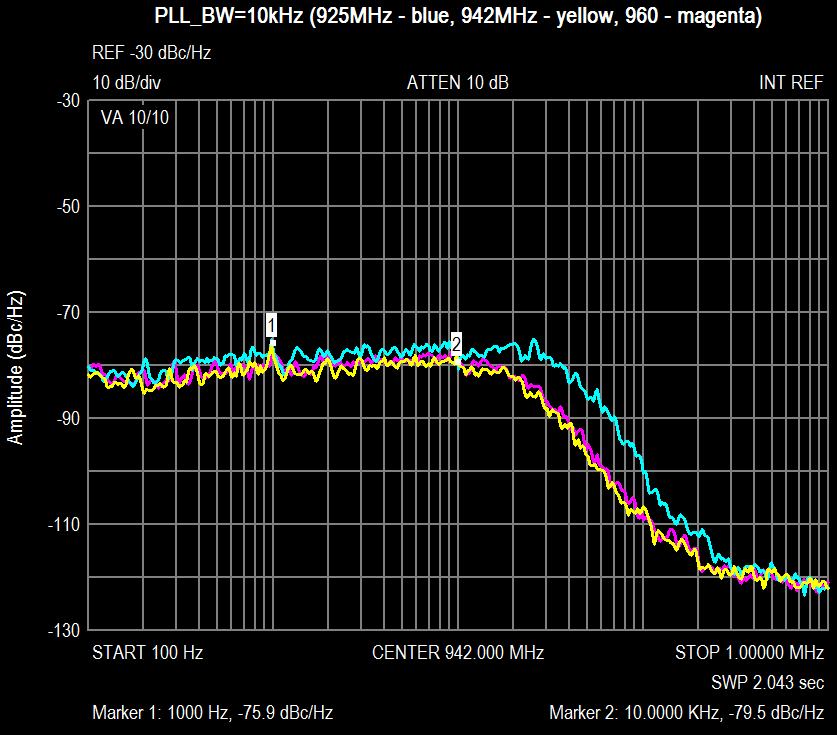
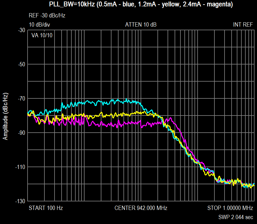
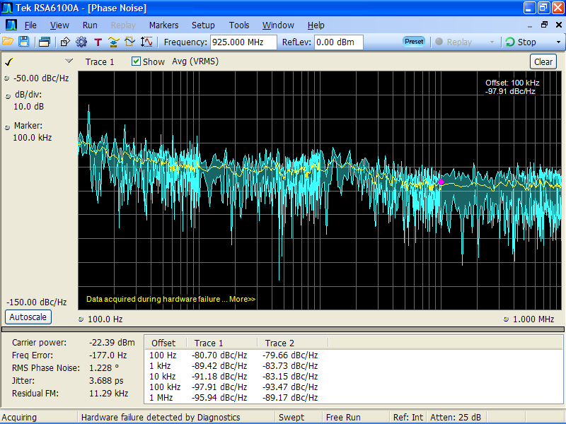
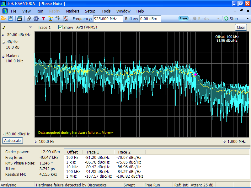
I couldn't wait your reply and start to implement 10kHz BW of PLL. You can find here two pictures with results. First of all I found that PLL tuning algorithm doesn't work properly at low PLL BW. VCOCAP register (r0x19) should contain higher value at least for +3 units (to make CAP lower), otherwise freq's above 950MHz never locked. Note, that you should read and change register 0x19 after autotuning. Second, you can see some noise difference for the 925MHz because of used DIV=8 of the VCO, instead of DIV=4 for 942 and 960MHz. Third, you can see PLL noice dependance with the charge pump current (r0x16).
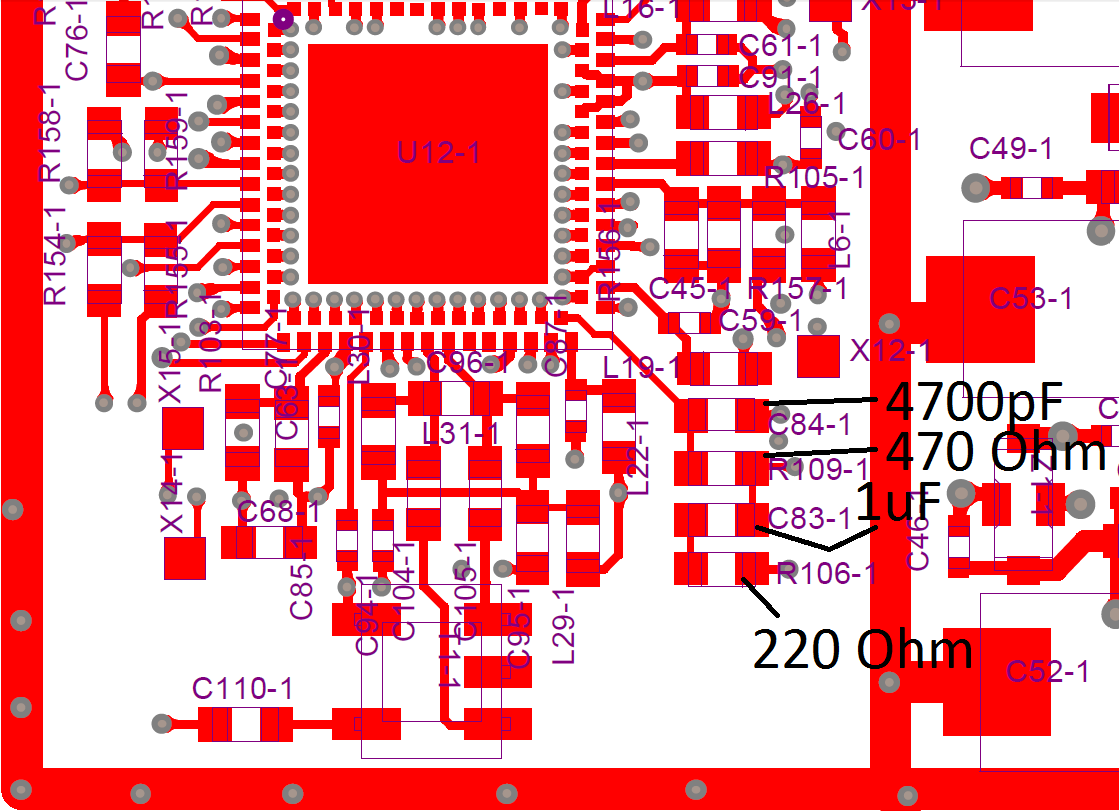
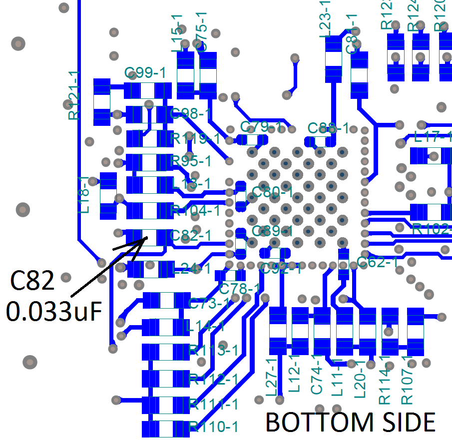
On the other two pictures you can find which components have to be changed. Thomas, please make one more measure of LO noise and jitter at PLL BW=10kHz by your instrument. We need to know, is it real to reach modulation accuracy of 1.5 degrees RMS or impossible, just because of LMS PLL have bigger jitter.
Best regards, Andrey Sviyazov.
2012/7/19 Andrey Sviyazov andrey.sviyazov@fairwaves.ru
Thomas. I've calculate few PIF filters for PLL by the ADIsimPLL and found that RMS phase jitter in case of 5kHz and 50kHz only 0.33 and 0.46 degrees. It is very small difference, so are you sure that I should implement 10kHz bandwidth filter as in USRP? Actually it is absolutly not an problem for me to implement it, but I have to be sure. I've calculated it for 10kHz bandwidth, noise plot will be around 75-80dBc/Hz @ 10kHz and 105-110 dBc/Hz @ 100kHz offset.
Best regards, Andrey Sviyazov.
2012/7/19 Andrey Sviyazov andrey.sviyazov@fairwaves.ru
Alexander. I think that few pulses of LMS hardware reset (LMS_NRST-1 and LMS_NRST-2 pins) will be much easily than all registers checking. BTW, are there reset pulses after power up or not?
Best regards, Andrey Sviyazov.
2012/7/19 Alexander Chemeris alexander.chemeris@gmail.com
Guys, please keep track of all LMS configuration values which are not set to default during power on and we'll add them to our manual initialization script.
On Thu, Jul 19, 2012 at 6:56 PM, Andrey Sviyazov andrey.sviyazov@fairwaves.ru wrote:
Sergey. I'll play around GPS power and RTC supply, thank you for your help.
Thomas. About r0x16 please be sure that sometimes it isn't set to default value after power up (I saw it few times). Also I think that possible those bad "power on reset" gave us unstable result of LMS autocalibration.
Best regards, Andrey Sviyazov.
2012/7/19 sergey kostanbaev sergey.kostanbaev@gmail.com
Which gives ~1.5khz cut-off, that's strange
Also I'd check GPS VDD and AVDD nosies
On Thu, Jul 19, 2012 at 6:41 PM, Andrey Sviyazov andrey.sviyazov@fairwaves.ru wrote:
1kOhm resistor and 0.1uF capacitor already exist between DAC and VC input. Of course I'll increase capacitance or resistance to be sure about VC pin.
Best regards, Andrey Sviyazov.
2012/7/19 sergey kostanbaev sergey.kostanbaev@gmail.com > > No :) But it may cause. > > I'd check all the line from FPGA to DAC to VCTXCO because VC pin is > really sensible to any noise. > - caused by power supply of DAC. > - output noise of DAC. > - algorithm of changing values > > At first I'd inspect VC pin at VCTXCO and try to filter it with
cut-off
> frequency 1-0.1 Hz > > > On Thu, Jul 19, 2012 at 6:29 PM, Andrey Sviyazov > andrey.sviyazov@fairwaves.ru wrote: >> >> Sergey. >> Is it really so frequently (32k/s updates at 1pps reference)? >> >> Best regards, >> Andrey Sviyazov. >> >> >> >> 2012/7/19 sergey kostanbaev sergey.kostanbaev@gmail.com >>> >>> >>> >>> On Thu, Jul 19, 2012 at 6:10 PM, Andrey Sviyazov >>> andrey.sviyazov@fairwaves.ru wrote: >>>> >>>> Hi all. >>>> >>>> I've found spurs on the LO noise plot at ~33kHz and ~66kHz
offset
>>>> when GPS antenna used and position locked. >>>> This spurs begin grow up when GPS just near to lock position and >>>> after locking spurs stopped to grow as you can see at picture. >>>> If thereafter GPS disconnected then noise coming back to normal
plot.
>>>> I think that it is result of 32768Hz clock in the GPS module
EB-230,
>>>> but can't understant how it can impact to 26MHz clock or VCO. >>> >>> >>> As another idea it can be caused by continues GPS correction lead
to
>>> DAC changes to the VCTXCO. >>> >>>> >>>> Please tell me something who know. >>>> >>>> Thomas. >>>> Was GPS antenna connected when noise measured like on the picture >>>> which you sent us (also attached here)? >>>> I would to know because of anomal peak near to 30kHz offset too. >>>> >>>> Best regards, >>>> Andrey Sviyazov. >>>> >>>> >>>> >>>> 2012/7/19 Andrey Sviyazov andrey.sviyazov@fairwaves.ru >>>>> >>>>> Sorry, that was meant to be sent to the mailing list :) >>>>> >>>>> Best regards, >>>>> Andrey Sviyazov. >>>>> >>>>> ---------- Forwarded message ---------- >>>>> From: Andrey Sviyazov andreysviyaz@gmail.com >>>>> Date: 2012/7/18 >>>>> Subject: LMS TxLO noise >>>>> >>>>> Hi Thomas. >>>>> >>>>> Here forwarded my last e-mail with noise plots when I stopped
work
>>>>> around it at first time, please see below. >>>>> >>>>> Please try to play around Tx PLL charge pump current (register
0x16)
>>>>> for better RMS phase stability. >>>>> I think we should reach 1 degree or below. >>>>> >>>>> Alexander gave me the second UmTRX board and after checking and >>>>> fixing all known hardware issues I've got roughly the same LO
noise plot.
>>>>> Possible Robin had no time to fixing all of our issues, so check >>>>> them all please. >>>>> And also check please what type of TCXO installed on your board. >>>>> >>>>> Best regards, >>>>> Andrey Sviyazov. >>>>> >>>>> ---------- Forwarded message ---------- >>>>> From: Andrey Sviyazov andreysviyaz@gmail.com >>>>> Date: 2012/4/13 >>>>> Subject: Re: LMS TxLO noise >>>>> >>>>> Hi all. >>>>> >>>>> There is progress with LMS PLL :) >>>>> Pictures are attached here. >>>>> t was discovered that 80 kHz spurs come from Ethernet, or rather >>>>> from the ET1011. >>>>> I unknowingly put the choke between transistor of 1V regulator
and
>>>>> analog power 1V. >>>>> As a result, the regulator has become unstable and oscillated
80 kHz
>>>>> with amplitude of 200 mV, which climbed into the LMS PLL. >>>>> To correct this problem L46 should be replaced by jumper on all
alfa
>>>>> version PCB's. >>>>> >>>>> Also I just played with current in the PLL loop, shown on the >>>>> picture for clarity. >>>>> Proved to be the optimal current 1,9 mA (you should write 0x93
in
>>>>> the register of 0x16). >>>>> But, I think, for the RxPLL will be better use of the current
2.4
>>>>> mA, because the nearest noises more important for Rx (you
should write 0x98
>>>>> in the register 0x26). >>>>> >>>>> Best regards, >>>>> Andrey Sviyazov. >>>>> >>>>> >>>> >>> >> >
-- Regards, Alexander Chemeris. CEO, Fairwaves LLC / ООО УмРадио http://fairwaves.ru
Andrew,
On Thu, Jul 19, 2012 at 5:33 PM, Andrey Sviyazov andrey.sviyazov@fairwaves.ru wrote:
I think that few pulses of LMS hardware reset (LMS_NRST-1 and LMS_NRST-2 pins) will be much easily than all registers checking. BTW, are there reset pulses after power up or not?
Do we pulse those reset pins on a hardware reset? I think we should have a way to perform this reset from software as well.
Hi Andrey,
Sorry I did answer sooner. The E4406A arrived so I have been setting that up. I have UmTRX hooked up right now, which I will be testing very shortly.
Thomas
On Fri, Jul 20, 2012 at 1:14 PM, Andrey Sviyazov andrey.sviyazov@fairwaves.ru wrote:
Hi Thomas.
I couldn't wait your reply and start to implement 10kHz BW of PLL. You can find here two pictures with results. First of all I found that PLL tuning algorithm doesn't work properly at low PLL BW. VCOCAP register (r0x19) should contain higher value at least for +3 units (to make CAP lower), otherwise freq's above 950MHz never locked. Note, that you should read and change register 0x19 after autotuning. Second, you can see some noise difference for the 925MHz because of used DIV=8 of the VCO, instead of DIV=4 for 942 and 960MHz. Third, you can see PLL noice dependance with the charge pump current (r0x16).
On the other two pictures you can find which components have to be changed. Thomas, please make one more measure of LO noise and jitter at PLL BW=10kHz by your instrument. We need to know, is it real to reach modulation accuracy of 1.5 degrees RMS or impossible, just because of LMS PLL have bigger jitter.
Best regards, Andrey Sviyazov.
2012/7/19 Andrey Sviyazov andrey.sviyazov@fairwaves.ru
Thomas. I've calculate few PIF filters for PLL by the ADIsimPLL and found that RMS phase jitter in case of 5kHz and 50kHz only 0.33 and 0.46 degrees. It is very small difference, so are you sure that I should implement 10kHz bandwidth filter as in USRP? Actually it is absolutly not an problem for me to implement it, but I have to be sure. I've calculated it for 10kHz bandwidth, noise plot will be around 75-80dBc/Hz @ 10kHz and 105-110 dBc/Hz @ 100kHz offset.
Best regards, Andrey Sviyazov.
2012/7/19 Andrey Sviyazov andrey.sviyazov@fairwaves.ru
Alexander. I think that few pulses of LMS hardware reset (LMS_NRST-1 and LMS_NRST-2 pins) will be much easily than all registers checking. BTW, are there reset pulses after power up or not?
Best regards, Andrey Sviyazov.
2012/7/19 Alexander Chemeris alexander.chemeris@gmail.com
Guys, please keep track of all LMS configuration values which are not set to default during power on and we'll add them to our manual initialization script.
On Thu, Jul 19, 2012 at 6:56 PM, Andrey Sviyazov andrey.sviyazov@fairwaves.ru wrote:
Sergey. I'll play around GPS power and RTC supply, thank you for your help.
Thomas. About r0x16 please be sure that sometimes it isn't set to default value after power up (I saw it few times). Also I think that possible those bad "power on reset" gave us unstable result of LMS autocalibration.
Best regards, Andrey Sviyazov.
2012/7/19 sergey kostanbaev sergey.kostanbaev@gmail.com
Which gives ~1.5khz cut-off, that's strange
Also I'd check GPS VDD and AVDD nosies
On Thu, Jul 19, 2012 at 6:41 PM, Andrey Sviyazov andrey.sviyazov@fairwaves.ru wrote: > > 1kOhm resistor and 0.1uF capacitor already exist between DAC and VC > input. > Of course I'll increase capacitance or resistance to be sure about > VC > pin. > > Best regards, > Andrey Sviyazov. > > > > 2012/7/19 sergey kostanbaev sergey.kostanbaev@gmail.com >> >> No :) But it may cause. >> >> I'd check all the line from FPGA to DAC to VCTXCO because VC pin is >> really sensible to any noise. >> - caused by power supply of DAC. >> - output noise of DAC. >> - algorithm of changing values >> >> At first I'd inspect VC pin at VCTXCO and try to filter it with >> cut-off >> frequency 1-0.1 Hz >> >> >> On Thu, Jul 19, 2012 at 6:29 PM, Andrey Sviyazov >> andrey.sviyazov@fairwaves.ru wrote: >>> >>> Sergey. >>> Is it really so frequently (32k/s updates at 1pps reference)? >>> >>> Best regards, >>> Andrey Sviyazov. >>> >>> >>> >>> 2012/7/19 sergey kostanbaev sergey.kostanbaev@gmail.com >>>> >>>> >>>> >>>> On Thu, Jul 19, 2012 at 6:10 PM, Andrey Sviyazov >>>> andrey.sviyazov@fairwaves.ru wrote: >>>>> >>>>> Hi all. >>>>> >>>>> I've found spurs on the LO noise plot at ~33kHz and ~66kHz >>>>> offset >>>>> when GPS antenna used and position locked. >>>>> This spurs begin grow up when GPS just near to lock position and >>>>> after locking spurs stopped to grow as you can see at picture. >>>>> If thereafter GPS disconnected then noise coming back to normal >>>>> plot. >>>>> I think that it is result of 32768Hz clock in the GPS module >>>>> EB-230, >>>>> but can't understant how it can impact to 26MHz clock or VCO. >>>> >>>> >>>> As another idea it can be caused by continues GPS correction lead >>>> to >>>> DAC changes to the VCTXCO. >>>> >>>>> >>>>> Please tell me something who know. >>>>> >>>>> Thomas. >>>>> Was GPS antenna connected when noise measured like on the >>>>> picture >>>>> which you sent us (also attached here)? >>>>> I would to know because of anomal peak near to 30kHz offset too. >>>>> >>>>> Best regards, >>>>> Andrey Sviyazov. >>>>> >>>>> >>>>> >>>>> 2012/7/19 Andrey Sviyazov andrey.sviyazov@fairwaves.ru >>>>>> >>>>>> Sorry, that was meant to be sent to the mailing list :) >>>>>> >>>>>> Best regards, >>>>>> Andrey Sviyazov. >>>>>> >>>>>> ---------- Forwarded message ---------- >>>>>> From: Andrey Sviyazov andreysviyaz@gmail.com >>>>>> Date: 2012/7/18 >>>>>> Subject: LMS TxLO noise >>>>>> >>>>>> Hi Thomas. >>>>>> >>>>>> Here forwarded my last e-mail with noise plots when I stopped >>>>>> work >>>>>> around it at first time, please see below. >>>>>> >>>>>> Please try to play around Tx PLL charge pump current (register >>>>>> 0x16) >>>>>> for better RMS phase stability. >>>>>> I think we should reach 1 degree or below. >>>>>> >>>>>> Alexander gave me the second UmTRX board and after checking and >>>>>> fixing all known hardware issues I've got roughly the same LO >>>>>> noise plot. >>>>>> Possible Robin had no time to fixing all of our issues, so >>>>>> check >>>>>> them all please. >>>>>> And also check please what type of TCXO installed on your >>>>>> board. >>>>>> >>>>>> Best regards, >>>>>> Andrey Sviyazov. >>>>>> >>>>>> ---------- Forwarded message ---------- >>>>>> From: Andrey Sviyazov andreysviyaz@gmail.com >>>>>> Date: 2012/4/13 >>>>>> Subject: Re: LMS TxLO noise >>>>>> >>>>>> Hi all. >>>>>> >>>>>> There is progress with LMS PLL :) >>>>>> Pictures are attached here. >>>>>> t was discovered that 80 kHz spurs come from Ethernet, or >>>>>> rather >>>>>> from the ET1011. >>>>>> I unknowingly put the choke between transistor of 1V regulator >>>>>> and >>>>>> analog power 1V. >>>>>> As a result, the regulator has become unstable and oscillated >>>>>> 80 kHz >>>>>> with amplitude of 200 mV, which climbed into the LMS PLL. >>>>>> To correct this problem L46 should be replaced by jumper on all >>>>>> alfa >>>>>> version PCB's. >>>>>> >>>>>> Also I just played with current in the PLL loop, shown on the >>>>>> picture for clarity. >>>>>> Proved to be the optimal current 1,9 mA (you should write 0x93 >>>>>> in >>>>>> the register of 0x16). >>>>>> But, I think, for the RxPLL will be better use of the current >>>>>> 2.4 >>>>>> mA, because the nearest noises more important for Rx (you >>>>>> should write 0x98 >>>>>> in the register 0x26). >>>>>> >>>>>> Best regards, >>>>>> Andrey Sviyazov. >>>>>> >>>>>> >>>>> >>>> >>> >> >
-- Regards, Alexander Chemeris. CEO, Fairwaves LLC / ООО УмРадио http://fairwaves.ru
On Fri, Jul 20, 2012 at 1:14 PM, Andrey Sviyazov andrey.sviyazov@fairwaves.ru wrote:
Hi Thomas.
I couldn't wait your reply and start to implement 10kHz BW of PLL. You can find here two pictures with results. First of all I found that PLL tuning algorithm doesn't work properly at low PLL BW. VCOCAP register (r0x19) should contain higher value at least for +3 units (to make CAP lower), otherwise freq's above 950MHz never locked. Note, that you should read and change register 0x19 after autotuning. Second, you can see some noise difference for the 925MHz because of used DIV=8 of the VCO, instead of DIV=4 for 942 and 960MHz. Third, you can see PLL noice dependance with the charge pump current (r0x16).
On the other two pictures you can find which components have to be changed. Thomas, please make one more measure of LO noise and jitter at PLL BW=10kHz by your instrument. We need to know, is it real to reach modulation accuracy of 1.5 degrees RMS or impossible, just because of LMS PLL have bigger jitter.
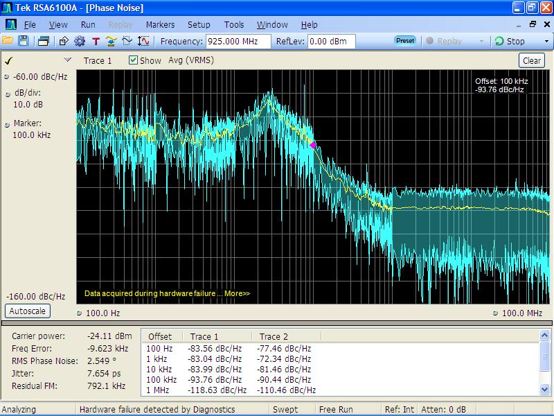
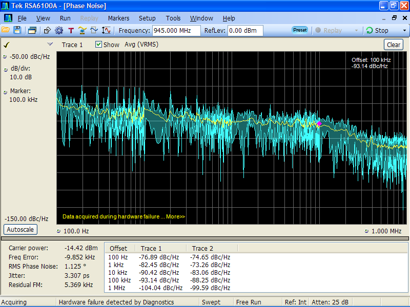
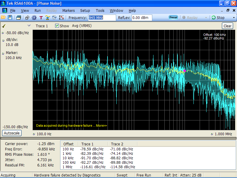
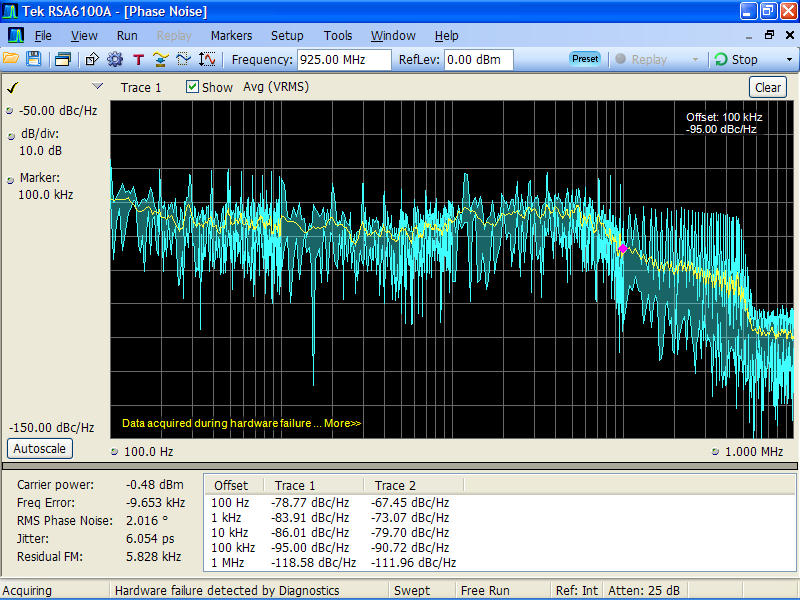
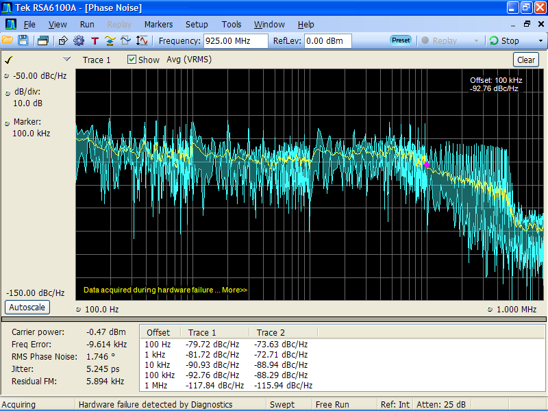
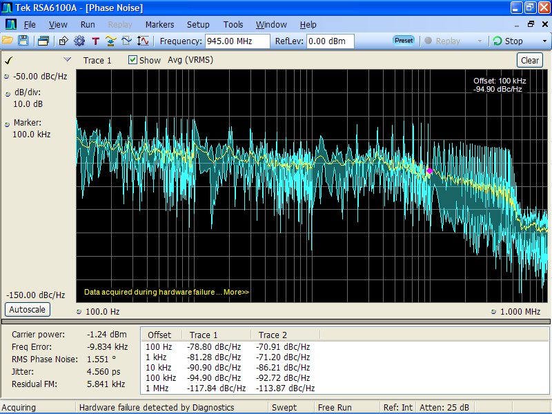
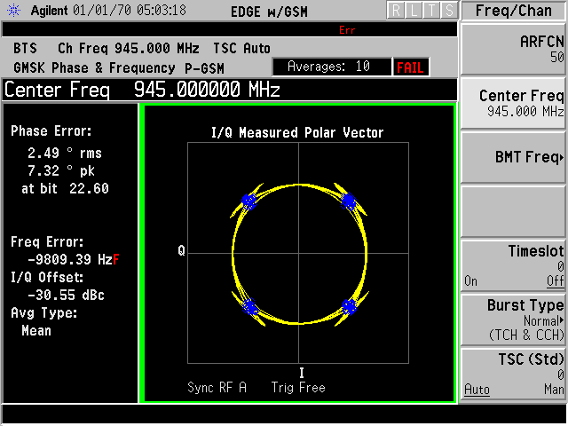
Here are phase noise plots with following settings measured at 925 MHz and 945 MHz.
--reg 0x16 --data 0x93 --reg 0x26 --data 0x98
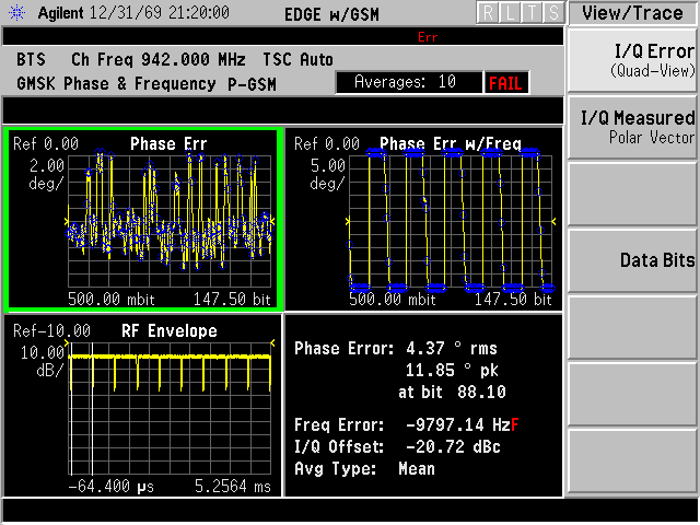
Charge pump current had a definite effect as did changing the frequency. Measured on the E4406A, phase error is quite high. There are still other calibration issues, but phase noise is probably still a concern. I also still have errors with auto calibration.
Note that USRP1 - with better phase noise - does not reach < 1.5 degree error, but is close at < 2.0 degrees RMS.
I'm currently going through the previous issues. If there is anything else I should examine or test, let me know.
Thomas
Hi Thomas.
First of all thank you very much.
And of course few questions: 1 why you use too small input signal to the analyser? I saw -120dBc/Hz @ 1MHz offset. 2 do you test LO with small CP current? 3 I don't see now noise peak @ 30kHz. Do you change something? 4 can 4406 measuring noise plot with log freq? 5 what type of modulation you use now? I mean 1 sps or 2?
Best regards, Andrey Sviyazov. (Sent from my mobile client) 21.07.2012 0:23 пользователь "Thomas Tsou" thomastsou@gmail.com написал:
On Fri, Jul 20, 2012 at 1:14 PM, Andrey Sviyazov andrey.sviyazov@fairwaves.ru wrote:
Hi Thomas.
I couldn't wait your reply and start to implement 10kHz BW of PLL. You can find here two pictures with results. First of all I found that PLL tuning algorithm doesn't work properly at
low
PLL BW. VCOCAP register (r0x19) should contain higher value at least for +3 units (to make CAP lower), otherwise freq's above 950MHz never locked. Note, that you should read and change register 0x19 after autotuning. Second, you can see some noise difference for the 925MHz because of used DIV=8 of the VCO, instead of DIV=4 for 942 and 960MHz. Third, you can see PLL noice dependance with the charge pump current (r0x16).
On the other two pictures you can find which components have to be
changed.
Thomas, please make one more measure of LO noise and jitter at PLL
BW=10kHz
by your instrument. We need to know, is it real to reach modulation accuracy of 1.5 degrees
RMS
or impossible, just because of LMS PLL have bigger jitter.
Here are phase noise plots with following settings measured at 925 MHz and 945 MHz.
--reg 0x16 --data 0x93 --reg 0x26 --data 0x98
Charge pump current had a definite effect as did changing the frequency. Measured on the E4406A, phase error is quite high. There are still other calibration issues, but phase noise is probably still a concern. I also still have errors with auto calibration.
Note that USRP1 - with better phase noise - does not reach < 1.5 degree error, but is close at < 2.0 degrees RMS.
I'm currently going through the previous issues. If there is anything else I should examine or test, let me know.
Thomas

4 can 4406 measuring noise plot with log freq?
To answer this: The E4406 can't do phase noise measurement directly from the interface, but there is an open source software that drives it over GPIB to do it : http://www.ke5fx.com/gpib/pn.htm
AFAIK you can't do it over the network interface with the original sw, but I have hacked together a small CLU to do it under linux. If you need it, I can send it to you.
Cheers,
Sylvain
On Fri, Jul 20, 2012 at 5:33 PM, Andrey Sviyazov andrey.sviyazov@fairwaves.ru wrote:
Hi Thomas.
First of all thank you very much.
And of course few questions: 1 why you use too small input signal to the analyser? I saw -120dBc/Hz @ 1MHz offset.
No reason. That's just how I had it setup at the time.
2 do you test LO with small CP current?
I went back and forth between default 0x8c and 0x93 values, which are attached for 925 and 945 MHz.
3 I don't see now noise peak @ 30kHz. Do you change something?
There is a drop in the 30 kHz peak when the frequency is at 945 MHz instead of 925.
4 can 4406 measuring noise plot with log freq?
Answered by Sylvain.
5 what type of modulation you use now? I mean 1 sps or 2?
4 sps with corrected pulse shape. The same configuration is below 2/5 on USRP1.
Thomas
On Fri, Jul 20, 2012 at 10:22 PM, Thomas Tsou thomastsou@gmail.com wrote:
There are still other calibration issues, but phase noise is probably still a concern.
You mean LO leakage and I/Q balance? Have you calibrated them? They're very easy to do - I could guide you with Skype if needed.
I also still have errors with auto calibration.
Well, you haven't enabled Rx chain in LMS and thus it's reasonable that Rx-related calibration is failing. You should do "--lms-rx-enable 1" before you try to do anything with Rx.
On Fri, Jul 20, 2012 at 6:09 PM, Alexander Chemeris alexander.chemeris@gmail.com wrote:
On Fri, Jul 20, 2012 at 10:22 PM, Thomas Tsou thomastsou@gmail.com wrote:
There are still other calibration issues, but phase noise is probably still a concern.
You mean LO leakage and I/Q balance? Have you calibrated them? They're very easy to do - I could guide you with Skype if needed.
LO leakage is calibrated. I/Q balance is not. Are there steps for this somewhere? I read 4.10 in the calibration guide, but I'm still not sure how to proceed.
I also still have errors with auto calibration.
Well, you haven't enabled Rx chain in LMS and thus it's reasonable that Rx-related calibration is failing. You should do "--lms-rx-enable 1" before you try to do anything with Rx.
Hmm. Similar error.
Thomas
On Fri, Jul 20, 2012 at 6:44 PM, Thomas Tsou thomastsou@gmail.com wrote:
On Fri, Jul 20, 2012 at 6:09 PM, Alexander Chemeris alexander.chemeris@gmail.com wrote:
Well, you haven't enabled Rx chain in LMS and thus it's reasonable that Rx-related calibration is failing. You should do "--lms-rx-enable 1" before you try to do anything with Rx.
Hmm. Similar error.
Occurs only on LMS 1. No errors when I run the same sequence on LMS 2.
Thomas
On Fri, Jul 20, 2012 at 6:55 PM, Thomas Tsou thomastsou@gmail.com wrote:
On Fri, Jul 20, 2012 at 6:44 PM, Thomas Tsou thomastsou@gmail.com wrote:
On Fri, Jul 20, 2012 at 6:09 PM, Alexander Chemeris alexander.chemeris@gmail.com wrote:
Well, you haven't enabled Rx chain in LMS and thus it's reasonable that Rx-related calibration is failing. You should do "--lms-rx-enable 1" before you try to do anything with Rx.
Hmm. Similar error.
Occurs only on LMS 1. No errors when I run the same sequence on LMS 2.
Also, I didn't realize that TX LPF DC calibration actually completed in the first error log - it usually doesn't. Sorry for the confusion. I believe it is similar to the tuning issue I'm seeing. If I keep power cycling then TX calibration will eventually work. Still no luck with Rx auto-calibration though.
Thomas
I tried calibrating LO leakage cancellation again and found out that it wasn't calibrated enough. The settings are very sensitive and increasing the I and Q shifts by one made a large difference on the E4406. The RSA seems to compensate, though, because the same changes don't affect it at all.
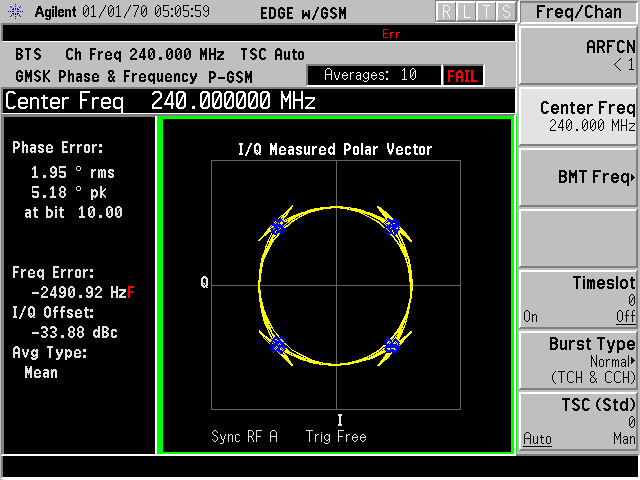
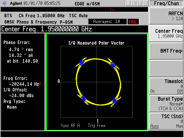
I also tried some different frequencies. At the not useful frequency of 240 MHz, we are not far from target values. At 945 MHz, it is better than before, but still too high. The 1900 MHz band is not so good.
Attached measurements are all at 4 sps, with the updated linear pulse from yesterday. I played more with the CP setting; the value of 0x93 provided the best measurements.
Thomas
On Sat, Jul 21, 2012 at 7:03 AM, Thomas Tsou thomastsou@gmail.com wrote:
I tried calibrating LO leakage cancellation again and found out that it wasn't calibrated enough. The settings are very sensitive and increasing the I and Q shifts by one made a large difference on the E4406.
This is my experience as well. Near the optimum point even change of calibration registers by 1 makes big difference. When you're far off, a change of a calibration register could be almost unnoticeable.
I've started adding notes about LMS calibration here: http://code.google.com/p/umtrx/wiki/LMS6002DCalibration Please write down there all useful notes about all types of calibration we're doing.
The RSA seems to compensate, though, because the same changes don't affect it at all.
How could it compensate? For RSA it should look like a genuine sine signal.
I also tried some different frequencies. At the not useful frequency of 240 MHz, we are not far from target values. At 945 MHz, it is better than before, but still too high. The 1900 MHz band is not so good.
Well, we're more interested in GSM900, but this clearly shows that there is an issue with the LMS PLL noise.
On Sat, Jul 21, 2012 at 1:16 AM, Thomas Tsou thomastsou@gmail.com wrote:
On Fri, Jul 20, 2012 at 6:55 PM, Thomas Tsou thomastsou@gmail.com wrote:
On Fri, Jul 20, 2012 at 6:44 PM, Thomas Tsou thomastsou@gmail.com wrote:
On Fri, Jul 20, 2012 at 6:09 PM, Alexander Chemeris alexander.chemeris@gmail.com wrote:
Well, you haven't enabled Rx chain in LMS and thus it's reasonable that Rx-related calibration is failing. You should do "--lms-rx-enable 1" before you try to do anything with Rx.
Hmm. Similar error.
Occurs only on LMS 1. No errors when I run the same sequence on LMS 2.
Also, I didn't realize that TX LPF DC calibration actually completed in the first error log - it usually doesn't. Sorry for the confusion. I believe it is similar to the tuning issue I'm seeing.
Send me logs with a failed calibration as well, please - with register dumps as I described earlier.
On Sat, Jul 21, 2012 at 12:55 AM, Thomas Tsou thomastsou@gmail.com wrote:
On Fri, Jul 20, 2012 at 6:44 PM, Thomas Tsou thomastsou@gmail.com wrote:
On Fri, Jul 20, 2012 at 6:09 PM, Alexander Chemeris alexander.chemeris@gmail.com wrote:
Well, you haven't enabled Rx chain in LMS and thus it's reasonable that Rx-related calibration is failing. You should do "--lms-rx-enable 1" before you try to do anything with Rx.
Hmm. Similar error.
Occurs only on LMS 1. No errors when I run the same sequence on LMS 2.
Could you send me a register dump of both LMS'es with "--dump" to see whether there are any significant differences between register settings of two? I need dumps before and after every execution of 'umtrx_lms.py'.
On Sat, Jul 21, 2012 at 9:56 AM, Alexander Chemeris alexander.chemeris@gmail.com wrote:
On Sat, Jul 21, 2012 at 12:55 AM, Thomas Tsou thomastsou@gmail.com wrote:
On Fri, Jul 20, 2012 at 6:44 PM, Thomas Tsou thomastsou@gmail.com wrote:
On Fri, Jul 20, 2012 at 6:09 PM, Alexander Chemeris alexander.chemeris@gmail.com wrote:
Well, you haven't enabled Rx chain in LMS and thus it's reasonable that Rx-related calibration is failing. You should do "--lms-rx-enable 1" before you try to do anything with Rx.
Hmm. Similar error.
Occurs only on LMS 1. No errors when I run the same sequence on LMS 2.
Could you send me a register dump of both LMS'es with "--dump" to see whether there are any significant differences between register settings of two? I need dumps before and after every execution of 'umtrx_lms.py'.
Also, could you do this all with the attached patch which adds verbose debug?
On Sat, Jul 21, 2012 at 12:44 AM, Thomas Tsou thomastsou@gmail.com wrote:
On Fri, Jul 20, 2012 at 6:09 PM, Alexander Chemeris alexander.chemeris@gmail.com wrote:
On Fri, Jul 20, 2012 at 10:22 PM, Thomas Tsou thomastsou@gmail.com wrote:
I also still have errors with auto calibration.
Well, you haven't enabled Rx chain in LMS and thus it's reasonable that Rx-related calibration is failing. You should do "--lms-rx-enable 1" before you try to do anything with Rx.
Hmm. Similar error.
Hum. I just realized that we set register 0x09 to 0x80 in lms_init(), which means we set RXOUTSW to 1 and pins 113-116 of the chip are connected directly to the ADC. While this should not make any difference in theory, it's better to set this register to 0x00 on init to avoid any external interference.
One more interesting find is that EVB Quick Starter Manual recommends to power down SPI blocks inside of the chip if they're not used (see below). Could you try to set 0x09 register to 0x00 after the tuning and check whether it affects phase noise?
Clock Buffers control ----------------------------- Enable pins turn the internal clock buffers on and off. These should be enabled when control of the device is needed, however during operation SPI clocks which are not being used should be disabled to reduce the risk of SPI clock spurious.
On Sat, Jul 21, 2012 at 10:43 PM, Alexander Chemeris alexander.chemeris@gmail.com wrote:
On Sat, Jul 21, 2012 at 12:44 AM, Thomas Tsou thomastsou@gmail.com wrote:
On Fri, Jul 20, 2012 at 6:09 PM, Alexander Chemeris alexander.chemeris@gmail.com wrote:
On Fri, Jul 20, 2012 at 10:22 PM, Thomas Tsou thomastsou@gmail.com wrote:
I also still have errors with auto calibration.
Well, you haven't enabled Rx chain in LMS and thus it's reasonable that Rx-related calibration is failing. You should do "--lms-rx-enable 1" before you try to do anything with Rx.
Hmm. Similar error.
Hum. I just realized that we set register 0x09 to 0x80 in lms_init(), which means we set RXOUTSW to 1 and pins 113-116 of the chip are connected directly to the ADC. While this should not make any difference in theory, it's better to set this register to 0x00 on init to avoid any external interference.
Note, that I've checked in this change and now 0x09 is initialized to 0x00 in the fairwaves/umtrx branch.
On Sat, Jul 21, 2012 at 12:44 AM, Thomas Tsou thomastsou@gmail.com wrote:
On Fri, Jul 20, 2012 at 6:09 PM, Alexander Chemeris alexander.chemeris@gmail.com wrote:
On Fri, Jul 20, 2012 at 10:22 PM, Thomas Tsou thomastsou@gmail.com wrote:
There are still other calibration issues, but phase noise is probably still a concern.
You mean LO leakage and I/Q balance? Have you calibrated them? They're very easy to do - I could guide you with Skype if needed.
LO leakage is calibrated. I/Q balance is not. Are there steps for this somewhere? I read 4.10 in the calibration guide, but I'm still not sure how to proceed.
I've started documenting this at the wiki: http://code.google.com/p/umtrx/wiki/LMS6002DCalibration#Tx_I/Q_balance_calib... Is that a good enough description for you?
Note, that FPGA registers which control I/Q imbalance compensation has been changed in the commit which introduced dual-channel Tx: https://github.com/chemeris/UHD-Fairwaves/commit/3d80d881d82e93ed39e83f72d5e... Host side hasn't been updated to accommodate those register changes yet. I would appreciate if you could do that.
On Sat, Jul 21, 2012 at 5:57 PM, Alexander Chemeris alexander.chemeris@gmail.com wrote:
I've started documenting this at the wiki: http://code.google.com/p/umtrx/wiki/LMS6002DCalibration#Tx_I/Q_balance_calib... Is that a good enough description for you?
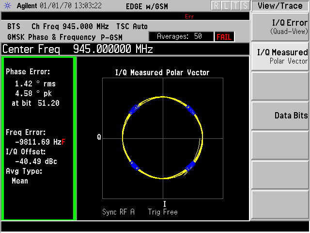
Added:
- IQ balance correction - Laurent C1 pulse
We are below the target threshold.
Thomas
On Sun, Jul 22, 2012 at 6:40 AM, Thomas Tsou thomastsou@gmail.com wrote:
On Sat, Jul 21, 2012 at 5:57 PM, Alexander Chemeris alexander.chemeris@gmail.com wrote:
I've started documenting this at the wiki: http://code.google.com/p/umtrx/wiki/LMS6002DCalibration#Tx_I/Q_balance_calib... Is that a good enough description for you?
Added:
- IQ balance correction
- Laurent C1 pulse
We are below the target threshold.
Great achievement! Is it consistent over the whole 900 band, i.e. is that the worst case?
I guess in 1800 band we're above the threshold yet. Could you measure by how much we're off there?
On Sun, Jul 22, 2012 at 12:59 AM, Alexander Chemeris alexander.chemeris@gmail.com wrote:
On Sun, Jul 22, 2012 at 6:40 AM, Thomas Tsou thomastsou@gmail.com wrote:
On Sat, Jul 21, 2012 at 5:57 PM, Alexander Chemeris alexander.chemeris@gmail.com wrote:
I've started documenting this at the wiki: http://code.google.com/p/umtrx/wiki/LMS6002DCalibration#Tx_I/Q_balance_calib... Is that a good enough description for you?
Added:
- IQ balance correction
- Laurent C1 pulse
We are below the target threshold.
Great achievement! Is it consistent over the whole 900 band, i.e. is that the worst case?
Overall measurements are close (either above or below) to 1.5/5 for the 900 band in general. 945 MHz is currently the best case, but that is the frequency I spent the most time on with calibration. Do we need to be consistently below 1.5/5 or just close?
I guess in 1800 band we're above the threshold yet. Could you measure by how much we're off there?
At 1945 MHz,the best I could do was roughly 2.3/7.2 with IQ balance and LO leakage corrections. I didn't try any 1800 band frequencies.
Thomas
On Sun, Jul 22, 2012 at 10:51 PM, Thomas Tsou thomastsou@gmail.com wrote:
On Sun, Jul 22, 2012 at 12:59 AM, Alexander Chemeris alexander.chemeris@gmail.com wrote:
On Sun, Jul 22, 2012 at 6:40 AM, Thomas Tsou thomastsou@gmail.com wrote:
On Sat, Jul 21, 2012 at 5:57 PM, Alexander Chemeris alexander.chemeris@gmail.com wrote:
I've started documenting this at the wiki: http://code.google.com/p/umtrx/wiki/LMS6002DCalibration#Tx_I/Q_balance_calib... Is that a good enough description for you?
Added:
- IQ balance correction
- Laurent C1 pulse
We are below the target threshold.
Great achievement! Is it consistent over the whole 900 band, i.e. is that the worst case?
Overall measurements are close (either above or below) to 1.5/5 for the 900 band in general. 945 MHz is currently the best case, but that is the frequency I spent the most time on with calibration. Do we need to be consistently below 1.5/5 or just close?
Thanks for the measurements. At the end we should be below that at all GSM bands. For now it's fine to be close.
I also noticed that your frequency is far off - could you calibrate it and make pictures of the best and worst case in the 900 band?
And just to be sure - could you check what TCXO do you have on the UmTRX? It should be TCD4029-26.0M, probably marked like PLEU4030Z.
On Sun, Jul 22, 2012 at 3:21 PM, Alexander Chemeris alexander.chemeris@gmail.com wrote:
On Sun, Jul 22, 2012 at 10:51 PM, Thomas Tsou thomastsou@gmail.com wrote:
Overall measurements are close (either above or below) to 1.5/5 for the 900 band in general. 945 MHz is currently the best case, but that is the frequency I spent the most time on with calibration. Do we need to be consistently below 1.5/5 or just close?
Thanks for the measurements. At the end we should be below that at all GSM bands. For now it's fine to be close.
I also noticed that your frequency is far off - could you calibrate it and make pictures of the best and worst case in the 900 band?
Perhaps this is a silly question, but how do I calibrate the clock? or use an external reference signal?
And just to be sure - could you check what TCXO do you have on the UmTRX? It should be TCD4029-26.0M, probably marked like PLEU4030Z.
2600 028 PLEU 4030Z
Thomas

On Jul 22, 2012 6:23 PM, "Sylvain Munaut" 246tnt@gmail.com wrote:
Perhaps this is a silly question, but how do I calibrate the clock? or use an external reference signal?
Plug a GPS antenna, wait for 5 min or so ...
That is rather challenging indoors.
Let me find out what antennas are on the roof. I'll just retune the LMS in the meantime.
Thomas
Thomas, thanks for file. But, may be you know, how to convert it to *.cfile for tx_samples_from_file.exe? Here attached zip with example of *.cfile which Alexander made for me in somewhere like MathLab, I think so. Rename zi_ to zip first.
Alexander, may be you know and then you can convert this file or part of it?
Overall measurements are close (either above or below) to 1.5/5 for
the 900 band in general. 945 MHz is currently the best case, but that is the frequency I spent the most time on with calibration. Do we need to be consistently below 1.5/5 or just close?
Thanks for the measurements. At the end we should be below that at all GSM bands. For now it's fine to be close.
I also noticed that your frequency is far off - could you calibrate it and make pictures of the best and worst case in the 900 band?
Perhaps this is a silly question, but how do I calibrate the clock? or use an external reference signal?
Actually you can tune LMS frequensy with 1Hz step to compensate known error.
Best regards, Andrey Sviyazov.
On Mon, Jul 23, 2012 at 2:17 AM, Thomas Tsou thomastsou@gmail.com wrote:
On Sun, Jul 22, 2012 at 3:21 PM, Alexander Chemeris alexander.chemeris@gmail.com wrote:
On Sun, Jul 22, 2012 at 10:51 PM, Thomas Tsou thomastsou@gmail.com wrote:
Overall measurements are close (either above or below) to 1.5/5 for the 900 band in general. 945 MHz is currently the best case, but that is the frequency I spent the most time on with calibration. Do we need to be consistently below 1.5/5 or just close?
Thanks for the measurements. At the end we should be below that at all GSM bands. For now it's fine to be close.
I also noticed that your frequency is far off - could you calibrate it and make pictures of the best and worst case in the 900 band?
Perhaps this is a silly question, but how do I calibrate the clock? or use an external reference signal?
Andrey Sviyazov - does ClockIn works as external input in UmTRXv1?
And just to be sure - could you check what TCXO do you have on the UmTRX? It should be TCD4029-26.0M, probably marked like PLEU4030Z.
2600 028 PLEU 4030Z
Ok, the correct one.
Perhaps this is a silly question, but how do I calibrate the clock? or use an external reference signal?
Andrey Sviyazov - does ClockIn works as external input in UmTRXv1?
Yes, 5V cmos level required or smaller with DC offset to get 2.5V symmetry. Turn switches to MHz and slave positions.
Best regards, Andrey Sviyazov. (Sent from my mobile client)
Hi Thomas.
Could you please make test again for LO integral phase noise and modulation accuracy with PLL loop filter 100kHz and ICP=0.4mA (or above), as Srdjan suggested us. I've assembled 100kHz loop filter with the next components: C82 = 100pF, C83=1500pF, C84=33pF, R106=2.2k, R109=3.3k. To get good noises replace choke L6 by capacitor 10nF..22nF and remove C45.
I ask you because I have to send final BOM as soon as possible to avoid delay of UmTRXv2 production due to changes for improvements.
Best regards, Andrey Sviyazov. P.S. Pictures attached just to be sure.
2012/7/23 Andrey Sviyazov andrey.sviyazov@fairwaves.ru
Perhaps this is a silly question, but how do I calibrate the clock? or use an external reference signal?
Andrey Sviyazov - does ClockIn works as external input in UmTRXv1?
Yes, 5V cmos level required or smaller with DC offset to get 2.5V symmetry. Turn switches to MHz and slave positions.
Best regards, Andrey Sviyazov. (Sent from my mobile client)
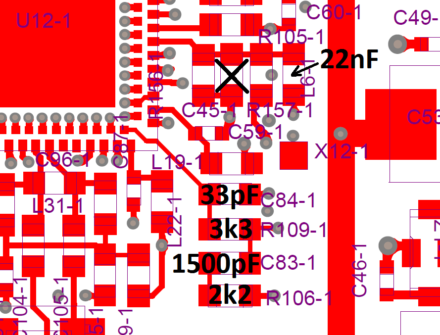
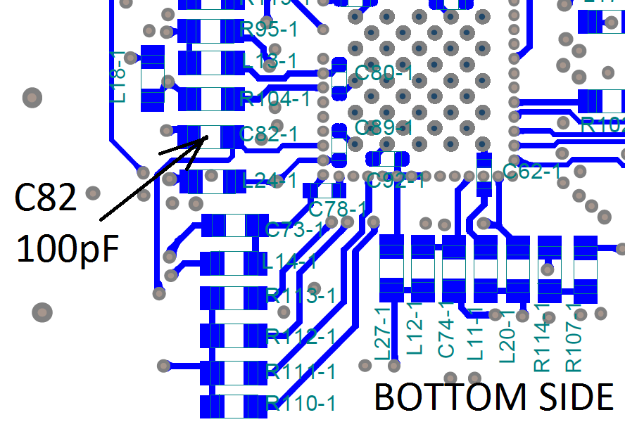
Hi Andrey,
I will need to order parts. Can you give me a list of digikey part numbers for the required components?
Thomas
On Tue, Jul 24, 2012 at 5:56 PM, Andrey Sviyazov andrey.sviyazov@fairwaves.ru wrote:
Hi Thomas.
Could you please make test again for LO integral phase noise and modulation accuracy with PLL loop filter 100kHz and ICP=0.4mA (or above), as Srdjan suggested us. I've assembled 100kHz loop filter with the next components: C82 = 100pF, C83=1500pF, C84=33pF, R106=2.2k, R109=3.3k. To get good noises replace choke L6 by capacitor 10nF..22nF and remove C45.
I ask you because I have to send final BOM as soon as possible to avoid delay of UmTRXv2 production due to changes for improvements.
Best regards, Andrey Sviyazov. P.S. Pictures attached just to be sure.
2012/7/23 Andrey Sviyazov andrey.sviyazov@fairwaves.ru
Perhaps this is a silly question, but how do I calibrate the clock? or use an external reference signal?
Andrey Sviyazov - does ClockIn works as external input in UmTRXv1?
Yes, 5V cmos level required or smaller with DC offset to get 2.5V symmetry. Turn switches to MHz and slave positions.
Best regards, Andrey Sviyazov. (Sent from my mobile client)
Hi Thomas.
Digikey part numbers links: C82 = 100pFhttp://www.digikey.com/product-detail/en/C0603C101J5GACTU/399-1061-1-ND/411336, C83=1500pFhttp://www.digikey.com/product-detail/en/C0603C152K5RACTU/399-1084-1-ND/411359, C84=33pFhttp://www.digikey.com/product-detail/en/C0603C330J5GACTU/399-1055-1-ND/411330, R106=2.2khttp://www.digikey.com/product-detail/en/RMCF0603JT2K20/RMCF0603JT2K20DKR-ND/1944084, R109=3.3khttp://www.digikey.com/product-detail/en/RMCF0603JT3K30/RMCF0603JT3K30CT-ND/1943182, L6=0.022uFhttp://www.digikey.com/product-detail/en/C0603C223K5RACTU/399-1280-1-ND/416056 .
But you'll remove 100pF capasitor from position C45, so you could use it for C82. BTW, how long time required to delivering from the DigiKey?
Best regards, Andrey Sviyazov.
2012/7/25 Thomas Tsou ttsou@vt.edu
Hi Andrey,
I will need to order parts. Can you give me a list of digikey part numbers for the required components?
Thomas
On Tue, Jul 24, 2012 at 5:56 PM, Andrey Sviyazov andrey.sviyazov@fairwaves.ru wrote:
Hi Thomas.
Could you please make test again for LO integral phase noise and
modulation
accuracy with PLL loop filter 100kHz and ICP=0.4mA (or above), as Srdjan suggested us. I've assembled 100kHz loop filter with the next components: C82 = 100pF, C83=1500pF, C84=33pF, R106=2.2k, R109=3.3k. To get good noises replace choke L6 by capacitor 10nF..22nF and remove
C45.
I ask you because I have to send final BOM as soon as possible to avoid delay of UmTRXv2 production due to changes for improvements.
Best regards, Andrey Sviyazov. P.S. Pictures attached just to be sure.
2012/7/23 Andrey Sviyazov andrey.sviyazov@fairwaves.ru
Perhaps this is a silly question, but how do I calibrate the clock?
or
use an external reference signal?
Andrey Sviyazov - does ClockIn works as external input in UmTRXv1?
Yes, 5V cmos level required or smaller with DC offset to get 2.5V symmetry. Turn switches to MHz and slave positions.
Best regards, Andrey Sviyazov. (Sent from my mobile client)
On Wed, Jul 25, 2012 at 1:41 PM, Andrey Sviyazov andrey.sviyazov@fairwaves.ru wrote:
Hi Thomas.
Digikey part numbers links: C82 = 100pF, C83=1500pF, C84=33pF, R106=2.2k, R109=3.3k, L6=0.022uF.
But you'll remove 100pF capasitor from position C45, so you could use it for C82. BTW, how long time required to delivering from the DigiKey?
Thank you for the links. Parts are ordered. Digikey orders usually arrives in 2 days.
Thomas
Hi Andrey,
Parts arrived yesterday and I made modifications for the 100 kHz loop filter and tested today. The entire 900 band is below 1.5 / 5 with a good margin.
http://filebox.vt.edu/users/ttsou/http/umtrx_945mhz_4.bmp
The lower part of the 1800 is also below the target value. I was not successful at 1885 MHz, though further calibration is possible (manual calibration at each frequency takes a very long time). I will perform additional tests tomorrow.
http://filebox.vt.edu/users/ttsou/http/umtrx_1825mhz_4.bmp http://filebox.vt.edu/users/ttsou/http/umtrx_1825mhz_noise.PNG
Thomas
On Wed, Jul 25, 2012 at 9:52 PM, Thomas Tsou ttsou@vt.edu wrote:
On Wed, Jul 25, 2012 at 1:41 PM, Andrey Sviyazov andrey.sviyazov@fairwaves.ru wrote:
Hi Thomas.
Digikey part numbers links: C82 = 100pF, C83=1500pF, C84=33pF, R106=2.2k, R109=3.3k, L6=0.022uF.
But you'll remove 100pF capasitor from position C45, so you could use it for C82. BTW, how long time required to delivering from the DigiKey?
Thank you for the links. Parts are ordered. Digikey orders usually arrives in 2 days.
Thomas
Hi Thomas.
Thank you very much for good news. Sylvain and everybody who discussed, thanks a lot. Seems, now I could finalize new revison of the BOM.
Best regards, Andrey Sviyazov.
2012/7/30 Thomas Tsou ttsou@vt.edu
Hi Andrey,
Parts arrived yesterday and I made modifications for the 100 kHz loop filter and tested today. The entire 900 band is below 1.5 / 5 with a good margin.
http://filebox.vt.edu/users/ttsou/http/umtrx_945mhz_4.bmp
The lower part of the 1800 is also below the target value. I was not successful at 1885 MHz, though further calibration is possible (manual calibration at each frequency takes a very long time). I will perform additional tests tomorrow.
http://filebox.vt.edu/users/ttsou/http/umtrx_1825mhz_4.bmp http://filebox.vt.edu/users/ttsou/http/umtrx_1825mhz_noise.PNG
Thomas
On Wed, Jul 25, 2012 at 9:52 PM, Thomas Tsou ttsou@vt.edu wrote:
On Wed, Jul 25, 2012 at 1:41 PM, Andrey Sviyazov andrey.sviyazov@fairwaves.ru wrote:
Hi Thomas.
Digikey part numbers links: C82 = 100pF, C83=1500pF, C84=33pF, R106=2.2k, R109=3.3k, L6=0.022uF.
But you'll remove 100pF capasitor from position C45, so you could use
it for
C82. BTW, how long time required to delivering from the DigiKey?
Thank you for the links. Parts are ordered. Digikey orders usually arrives in 2 days.
Thomas
Hi all,
Schematics are updated: https://github.com/chemeris/umtrx-schematics/commit/e4f71edbe96d4673ce87e6db...
Huge thanks to everyone for digging into the issue!
On Mon, Jul 30, 2012 at 12:07 PM, Andrey Sviyazov andrey.sviyazov@fairwaves.ru wrote:
Hi Thomas.
Thank you very much for good news. Sylvain and everybody who discussed, thanks a lot. Seems, now I could finalize new revison of the BOM.
Best regards, Andrey Sviyazov.
2012/7/30 Thomas Tsou ttsou@vt.edu
Hi Andrey,
Parts arrived yesterday and I made modifications for the 100 kHz loop filter and tested today. The entire 900 band is below 1.5 / 5 with a good margin.
http://filebox.vt.edu/users/ttsou/http/umtrx_945mhz_4.bmp
The lower part of the 1800 is also below the target value. I was not successful at 1885 MHz, though further calibration is possible (manual calibration at each frequency takes a very long time). I will perform additional tests tomorrow.
http://filebox.vt.edu/users/ttsou/http/umtrx_1825mhz_4.bmp http://filebox.vt.edu/users/ttsou/http/umtrx_1825mhz_noise.PNG
Thomas
On Wed, Jul 25, 2012 at 9:52 PM, Thomas Tsou ttsou@vt.edu wrote:
On Wed, Jul 25, 2012 at 1:41 PM, Andrey Sviyazov andrey.sviyazov@fairwaves.ru wrote:
Hi Thomas.
Digikey part numbers links: C82 = 100pF, C83=1500pF, C84=33pF, R106=2.2k, R109=3.3k, L6=0.022uF.
But you'll remove 100pF capasitor from position C45, so you could use it for C82. BTW, how long time required to delivering from the DigiKey?
Thank you for the links. Parts are ordered. Digikey orders usually arrives in 2 days.
Thomas
Hi Andrey,
Could you also describe to Thomas and Sylvain what to do with C45 and L6? I guess that's a required step before they do any other measurements.
And please, add this issue to the issue tracker.
On Wed, Jul 25, 2012 at 1:56 AM, Andrey Sviyazov andrey.sviyazov@fairwaves.ru wrote:
Hi Thomas.
Could you please make test again for LO integral phase noise and modulation accuracy with PLL loop filter 100kHz and ICP=0.4mA (or above), as Srdjan suggested us. I've assembled 100kHz loop filter with the next components: C82 = 100pF, C83=1500pF, C84=33pF, R106=2.2k, R109=3.3k. To get good noises replace choke L6 by capacitor 10nF..22nF and remove C45.
I ask you because I have to send final BOM as soon as possible to avoid delay of UmTRXv2 production due to changes for improvements.
Best regards, Andrey Sviyazov. P.S. Pictures attached just to be sure.
2012/7/23 Andrey Sviyazov andrey.sviyazov@fairwaves.ru
Perhaps this is a silly question, but how do I calibrate the clock? or use an external reference signal?
Andrey Sviyazov - does ClockIn works as external input in UmTRXv1?
Yes, 5V cmos level required or smaller with DC offset to get 2.5V symmetry. Turn switches to MHz and slave positions.
Best regards, Andrey Sviyazov. (Sent from my mobile client)
Alexander, I already explained it in preview mail.
Best regards, Andrey Sviyazov. (Sent from my mobile client) 25.07.2012 8:47 пользователь "Alexander Chemeris" < alexander.chemeris@gmail.com> написал:
Hi Andrey,
Could you also describe to Thomas and Sylvain what to do with C45 and L6? I guess that's a required step before they do any other measurements.
And please, add this issue to the issue tracker.
On Wed, Jul 25, 2012 at 1:56 AM, Andrey Sviyazov andrey.sviyazov@fairwaves.ru wrote:
Hi Thomas.
Could you please make test again for LO integral phase noise and
modulation
accuracy with PLL loop filter 100kHz and ICP=0.4mA (or above), as Srdjan suggested us. I've assembled 100kHz loop filter with the next components: C82 = 100pF, C83=1500pF, C84=33pF, R106=2.2k, R109=3.3k. To get good noises replace choke L6 by capacitor 10nF..22nF and remove
C45.
I ask you because I have to send final BOM as soon as possible to avoid delay of UmTRXv2 production due to changes for improvements.
Best regards, Andrey Sviyazov. P.S. Pictures attached just to be sure.
2012/7/23 Andrey Sviyazov andrey.sviyazov@fairwaves.ru
Perhaps this is a silly question, but how do I calibrate the clock?
or
use an external reference signal?
Andrey Sviyazov - does ClockIn works as external input in UmTRXv1?
Yes, 5V cmos level required or smaller with DC offset to get 2.5V symmetry. Turn switches to MHz and slave positions.
Best regards, Andrey Sviyazov. (Sent from my mobile client)
-- Regards, Alexander Chemeris. CEO, Fairwaves LLC / ООО УмРадио http://fairwaves.ru
Sorry, missed that! I was reading before I really wake up.
Still we need to document this at the issue tracker.
On Wed, Jul 25, 2012 at 9:01 AM, Andrey Sviyazov andrey.sviyazov@fairwaves.ru wrote:
Alexander, I already explained it in preview mail.
Best regards, Andrey Sviyazov. (Sent from my mobile client)
25.07.2012 8:47 пользователь "Alexander Chemeris" alexander.chemeris@gmail.com написал:
Hi Andrey,
Could you also describe to Thomas and Sylvain what to do with C45 and L6? I guess that's a required step before they do any other measurements.
And please, add this issue to the issue tracker.
On Wed, Jul 25, 2012 at 1:56 AM, Andrey Sviyazov andrey.sviyazov@fairwaves.ru wrote:
Hi Thomas.
Could you please make test again for LO integral phase noise and modulation accuracy with PLL loop filter 100kHz and ICP=0.4mA (or above), as Srdjan suggested us. I've assembled 100kHz loop filter with the next components: C82 = 100pF, C83=1500pF, C84=33pF, R106=2.2k, R109=3.3k. To get good noises replace choke L6 by capacitor 10nF..22nF and remove C45.
I ask you because I have to send final BOM as soon as possible to avoid delay of UmTRXv2 production due to changes for improvements.
Best regards, Andrey Sviyazov. P.S. Pictures attached just to be sure.
2012/7/23 Andrey Sviyazov andrey.sviyazov@fairwaves.ru
Perhaps this is a silly question, but how do I calibrate the clock? or use an external reference signal?
Andrey Sviyazov - does ClockIn works as external input in UmTRXv1?
Yes, 5V cmos level required or smaller with DC offset to get 2.5V symmetry. Turn switches to MHz and slave positions.
Best regards, Andrey Sviyazov. (Sent from my mobile client)
-- Regards, Alexander Chemeris. CEO, Fairwaves LLC / ООО УмРадио http://fairwaves.ru
Hi Thomas.
It is very good new. Please let us know more information how you wins! I mean which PLL filter, ICP and other LMS paremeters do you use or its done by just only IQ balance correction and Laurent C1 pulse and all other by default?
Best regards, Andrey Sviyazov.
2012/7/22 Thomas Tsou thomastsou@gmail.com
On Sat, Jul 21, 2012 at 5:57 PM, Alexander Chemeris alexander.chemeris@gmail.com wrote:
I've started documenting this at the wiki:
http://code.google.com/p/umtrx/wiki/LMS6002DCalibration#Tx_I/Q_balance_calib...
Is that a good enough description for you?
Added:
- IQ balance correction
- Laurent C1 pulse
We are below the target threshold.
Thomas
On Sun, Jul 22, 2012 at 10:12 AM, Andrey Sviyazov andrey.sviyazov@fairwaves.ru wrote:
Hi Thomas.
It is very good new. Please let us know more information how you wins! I mean which PLL filter, ICP and other LMS paremeters do you use or its done by just only IQ balance correction and Laurent C1 pulse and all other by default?
Register dump and startup sequence are attached. LO leakage was also recalibrated for different frequencies.
For comparison, after C1 pulse is added USRP1 is 1.3/3.5 and USRP2 is 1.2/3.0 when measured at 925 MHz.
Thomas
On Sun, Jul 22, 2012 at 11:11 PM, Thomas Tsou thomastsou@gmail.com wrote:
On Sun, Jul 22, 2012 at 10:12 AM, Andrey Sviyazov andrey.sviyazov@fairwaves.ru wrote:
Hi Thomas.
It is very good new. Please let us know more information how you wins! I mean which PLL filter, ICP and other LMS paremeters do you use or its done by just only IQ balance correction and Laurent C1 pulse and all other by default?
Register dump and startup sequence are attached.
Uhm, this is a register dump at what time? Originally I asked for the dump before and after every line in the umtrx_tx_init.sh.
LO leakage was also recalibrated for different frequencies.
How different are calibration values? I've never checked how is it related to the PLL frequency.
For comparison, after C1 pulse is added USRP1 is 1.3/3.5 and USRP2 is 1.2/3.0 when measured at 925 MHz.
tip: Would be great if you push this to github just as you send e-mail :)
PS Sylvain is waiting for a howto to run OpenBTS with UmTRX to test his setup.
On Sun, Jul 22, 2012 at 3:27 PM, Alexander Chemeris alexander.chemeris@gmail.com wrote:
On Sun, Jul 22, 2012 at 11:11 PM, Thomas Tsou thomastsou@gmail.com wrote:
On Sun, Jul 22, 2012 at 10:12 AM, Andrey Sviyazov andrey.sviyazov@fairwaves.ru wrote:
Hi Thomas.
It is very good new. Please let us know more information how you wins! I mean which PLL filter, ICP and other LMS paremeters do you use or its done by just only IQ balance correction and Laurent C1 pulse and all other by default?
Register dump and startup sequence are attached.
Uhm, this is a register dump at what time? Originally I asked for the dump before and after every line in the umtrx_tx_init.sh.
That was for Andrey. That dump was taken during the previous 945 MHz measurement.
These dumps are for the calibration failure, which are taken at the following points.
0 ./umtrx_lms.py --lms 1 --lms-init 1 ./umtrx_lms.py --lms 1 --lms-tx-enable 1 2 ./umtrx_lms.py --lms 1 --pll-ref-clock 26e6 --lpf-bandwidth-code 0x0f --lms-auto-calibration 3
LO leakage was also recalibrated for different frequencies.
How different are calibration values? I've never checked how is it related to the PLL frequency.
A single value within 900 MHz. At 1900 MHz it's maybe up to 3 or 4. LO leakage is easy to calibrate though. IQ calibration is rather tedious - calibration values at 900 MHz are useless at 1900 MHz.
For comparison, after C1 pulse is added USRP1 is 1.3/3.5 and USRP2 is 1.2/3.0 when measured at 925 MHz.
tip: Would be great if you push this to github just as you send e-mail :)
I'm posting the measurement captures and the Matlab for the pulse sequence generation. The transceiver code is pretty ugly right now. There are many stuffing bits and zero padding added to minimize the start / end error on the E4406. It may not even work with real phones now.
PS Sylvain is waiting for a howto to run OpenBTS with UmTRX to test his setup.
I'll hack something together later tonight. Can he receive a tone? If yes, then everything else is straightforward.
Thomas
Hi Thomas.
Could you please make an file from the OpenBTS stream as an cycled sequence to use with tx_samples_from_file.exe. I would like to test my UmTRX under windows with good instrument in Moscow (I hope to find it soon).
Best regards, Andrey Sviyazov.
2012/7/23 Thomas Tsou thomastsou@gmail.com
On Sun, Jul 22, 2012 at 3:27 PM, Alexander Chemeris alexander.chemeris@gmail.com wrote:
On Sun, Jul 22, 2012 at 11:11 PM, Thomas Tsou thomastsou@gmail.com
wrote:
On Sun, Jul 22, 2012 at 10:12 AM, Andrey Sviyazov andrey.sviyazov@fairwaves.ru wrote:
Hi Thomas.
It is very good new. Please let us know more information how you wins! I mean which PLL filter, ICP and other LMS paremeters do you use or
its done
by just only IQ balance correction and Laurent C1 pulse and all other
by
default?
Register dump and startup sequence are attached.
Uhm, this is a register dump at what time? Originally I asked for the dump before and after every line in the umtrx_tx_init.sh.
That was for Andrey. That dump was taken during the previous 945 MHz measurement.
These dumps are for the calibration failure, which are taken at the following points.
0 ./umtrx_lms.py --lms 1 --lms-init 1 ./umtrx_lms.py --lms 1 --lms-tx-enable 1 2 ./umtrx_lms.py --lms 1 --pll-ref-clock 26e6 --lpf-bandwidth-code 0x0f --lms-auto-calibration 3
LO leakage was also recalibrated for different frequencies.
How different are calibration values? I've never checked how is it related to the PLL frequency.
A single value within 900 MHz. At 1900 MHz it's maybe up to 3 or 4. LO leakage is easy to calibrate though. IQ calibration is rather tedious
- calibration values at 900 MHz are useless at 1900 MHz.
For comparison, after C1 pulse is added USRP1 is 1.3/3.5 and USRP2 is 1.2/3.0 when measured at 925 MHz.
tip: Would be great if you push this to github just as you send e-mail :)
I'm posting the measurement captures and the Matlab for the pulse sequence generation. The transceiver code is pretty ugly right now. There are many stuffing bits and zero padding added to minimize the start / end error on the E4406. It may not even work with real phones now.
PS Sylvain is waiting for a howto to run OpenBTS with UmTRX to test his
setup.
I'll hack something together later tonight. Can he receive a tone? If yes, then everything else is straightforward.
Thomas
On Sun, Jul 22, 2012 at 4:48 PM, Andrey Sviyazov andrey.sviyazov@fairwaves.ru wrote:
Hi Thomas.
Could you please make an file from the OpenBTS stream as an cycled sequence to use with tx_samples_from_file.exe. I would like to test my UmTRX under windows with good instrument in Moscow (I hope to find it soon).
OpenBTS output written to file at 4 sps / 1083.333 ksps. Tested on E4406.
https://github.com/downloads/ttsou/openbts-p2.8/capture.dat
Thomas
On Mon, Jul 23, 2012 at 3:07 AM, Thomas Tsou ttsou@vt.edu wrote:
On Jul 22, 2012 6:23 PM, "Sylvain Munaut" 246tnt@gmail.com wrote:
Perhaps this is a silly question, but how do I calibrate the clock? or use an external reference signal?
Plug a GPS antenna, wait for 5 min or so ...
That is rather challenging indoors.
Let me find out what antennas are on the roof. I'll just retune the LMS in the meantime.
You could also use host/utils/umtrx_vcxo.py to tune it manually.
On Mon, Jul 23, 2012 at 2:37 AM, Andrey Sviyazov andrey.sviyazov@fairwaves.ru wrote:
Thomas, thanks for file. But, may be you know, how to convert it to *.cfile for tx_samples_from_file.exe? Here attached zip with example of *.cfile which Alexander made for me in somewhere like MathLab, I think so. Rename zi_ to zip first.
Alexander, may be you know and then you can convert this file or part of it?
You do not need to convert, AFAIK.
Overall measurements are close (either above or below) to 1.5/5 for the 900 band in general. 945 MHz is currently the best case, but that is the frequency I spent the most time on with calibration. Do we need to be consistently below 1.5/5 or just close?
Thanks for the measurements. At the end we should be below that at all GSM bands. For now it's fine to be close.
I also noticed that your frequency is far off - could you calibrate it and make pictures of the best and worst case in the 900 band?
Perhaps this is a silly question, but how do I calibrate the clock? or use an external reference signal?
Actually you can tune LMS frequensy with 1Hz step to compensate known error.
This won't produce correct symbol speed.
-
 Alexander Chemeris
 -
 Andrey Sviyazov
 -
 sergey kostanbaev
 -
 Sylvain Munaut
 -
 Thomas Tsou
 -
 Thomas Tsou