
Hi Thomas,
If we get a UmTRX to you, could you make OpenBTS to run with it quickly, like before the end of the month? No matter how hackish the solution would be. We just need a way to start testing the hardware performance in a more real situation. Then we could target a cleaner solution.
To recap - right now we could transmit on a single channel, and receive on both channels, but the control of LMS chips is done by an external python script. I.e. to tune and set bandwidth, gain, etc you have to run this script before claiming a device with UHD.

On Sat, Jun 9, 2012 at 9:30 AM, Alexander Chemeris alexander.chemeris@gmail.com wrote:
Hi Thomas,
If we get a UmTRX to you, could you make OpenBTS to run with it quickly, like before the end of the month? No matter how hackish the solution would be. We just need a way to start testing the hardware performance in a more real situation. Then we could target a cleaner solution.
To recap - right now we could transmit on a single channel, and receive on both channels, but the control of LMS chips is done by an external python script. I.e. to tune and set bandwidth, gain, etc you have to run this script before claiming a device with UHD.
FYI, I was finishing plans to attend the openhere festival in Dublin at the end of the month. That is in two weeks.
What is the state of OpenBTS integration right now? Can you transmit a beacon signal? If UmTRX can support tuning, gain, and full duplex streaming with the existing UHD timestamp interface, then it shouldn't take long for OpenBTS. I can use any reasonable sample rate for testing.
Is the external python script in a repository?
Thomas
Hi Thomas,
On Sun, Jun 10, 2012 at 4:58 AM, Thomas Tsou thomastsou@gmail.com wrote:
On Sat, Jun 9, 2012 at 9:30 AM, Alexander Chemeris alexander.chemeris@gmail.com wrote:
Hi Thomas,
If we get a UmTRX to you, could you make OpenBTS to run with it quickly, like before the end of the month? No matter how hackish the solution would be. We just need a way to start testing the hardware performance in a more real situation. Then we could target a cleaner solution.
To recap - right now we could transmit on a single channel, and receive on both channels, but the control of LMS chips is done by an external python script. I.e. to tune and set bandwidth, gain, etc you have to run this script before claiming a device with UHD.
FYI, I was finishing plans to attend the openhere festival in Dublin at the end of the month. That is in two weeks.
Oh, that's great! So hopefully see you there! Andrey Sviyazov is going to be there as well.
What is the state of OpenBTS integration right now?
OpenBTS starts with this change:
diff --git a/Transceiver52M/UHDDevice.cpp b/Transceiver52M/UHDDevice.cpp index d4ba580..4baf824 100644 --- a/Transceiver52M/UHDDevice.cpp +++ b/Transceiver52M/UHDDevice.cpp @@ -48,7 +48,8 @@
tx_ampl - Transmit amplitude must be between 0 and 1.0 */ -const double master_clk_rt = 52e6; +//const double master_clk_rt = 52e6; +const double master_clk_rt = 13e6; const size_t smpl_buf_sz = (1 << 20); const float tx_ampl = .3;
But the behavior is a bit strange - when I start OpenBTS transceiver starts to consume 100% of CPU and doesn't transmit. After a while (a minute or so) CPU usage drops and I start seeing a signal at the UmTRX output. I had no time to look into this deeply.
Can you transmit a beacon signal?
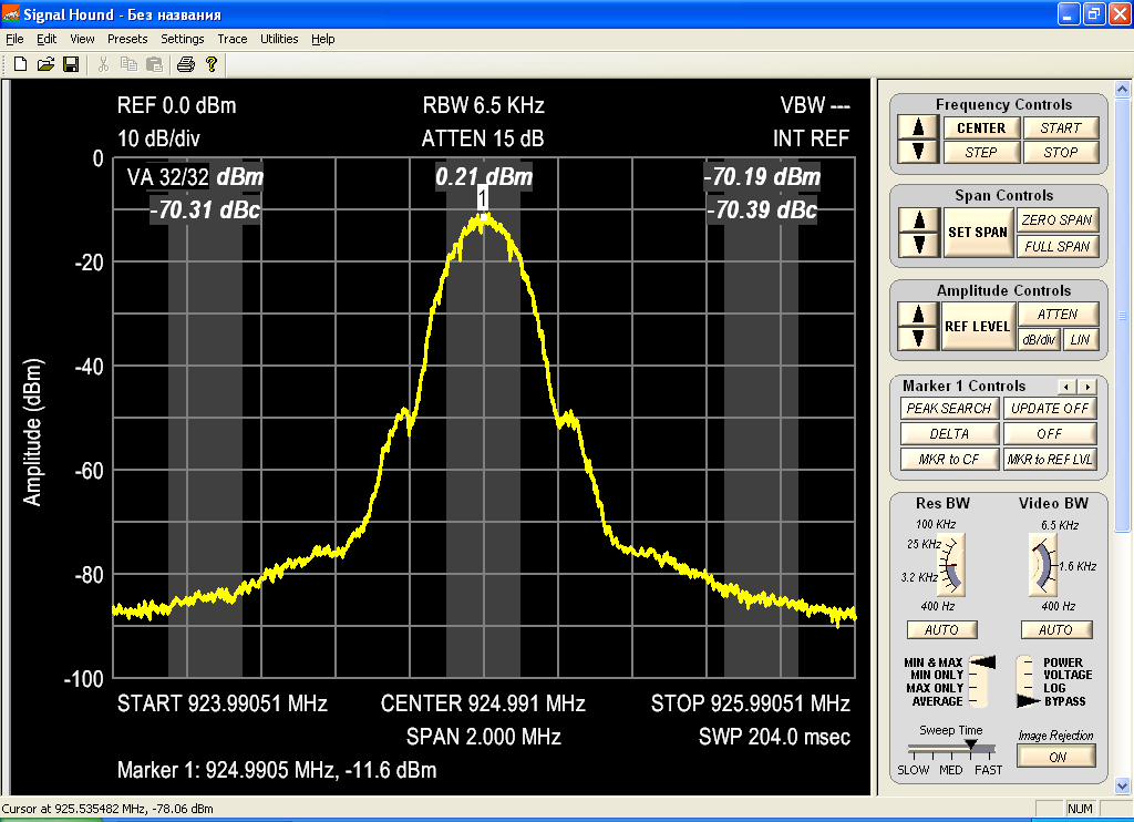
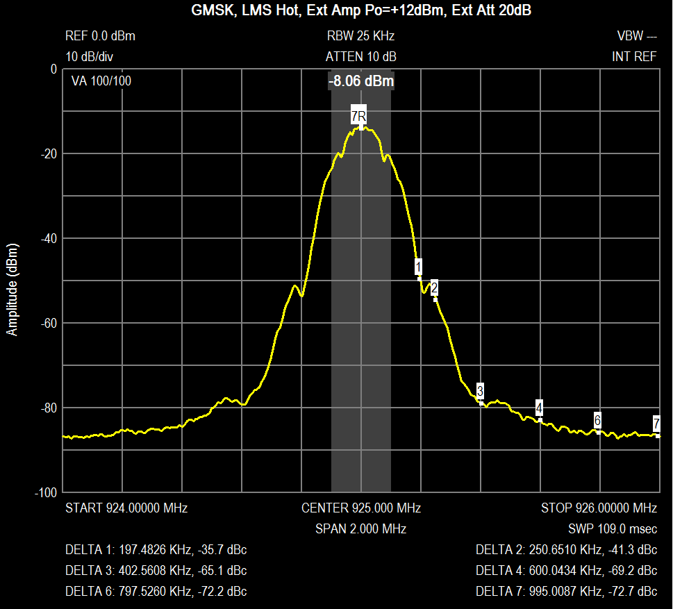
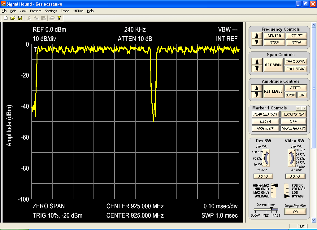
Yes. I could see the network with a phone. Signal hound pictures: 1) umtrx-openbts-spectrum.PNG - spectrum, generated by OpenBTS. 2) umtrx-openbts-timeslots.PNG - the same, but with zero span. 3) "GMSK VGA1 -5, VGA2 18, channel power 750kHz.PNG" and "Tx_GMSK#6(hot)_240412.png" are spectrum of a pure continuous GMSK signal, transmitted with UmTRX (captured by me and Andrey Sviyazov).
If UmTRX can support tuning, gain, and full duplex streaming with the existing UHD timestamp interface, then it shouldn't take long for OpenBTS.
Great!
Actually I should just try to run it - may be it will work right away? :)
I can use any reasonable sample rate for testing.
FYI: We use 13MHz
Is the external python script in a repository?
Yes. https://github.com/chemeris/UHD-Fairwaves/blob/fairwaves/umtrx-dboard/host/u...
Not everything is implemented, but it's easy to amend it.
On Sun, Jun 10, 2012 at 10:05 AM, Alexander Chemeris alexander.chemeris@gmail.com wrote:
OpenBTS starts with this change:
diff --git a/Transceiver52M/UHDDevice.cpp b/Transceiver52M/UHDDevice.cpp index d4ba580..4baf824 100644 --- a/Transceiver52M/UHDDevice.cpp +++ b/Transceiver52M/UHDDevice.cpp @@ -48,7 +48,8 @@
tx_ampl - Transmit amplitude must be between 0 and 1.0 */ -const double master_clk_rt = 52e6; +//const double master_clk_rt = 52e6; +const double master_clk_rt = 13e6; const size_t smpl_buf_sz = (1 << 20); const float tx_ampl = .3;
But the behavior is a bit strange - when I start OpenBTS transceiver starts to consume 100% of CPU and doesn't transmit. After a while (a minute or so) CPU usage drops and I start seeing a signal at the UmTRX output. I had no time to look into this deeply.
If the load drops down and the signal transmits, I wouldn't worry about it for now. The likely condition is that there is a offset between the initial arriving timestamp and the expected timestamp. Because the receive timestamps drive the transceiver, the receiver may run at 100% until the timestamp and expected value align. If OpenBTS transmits consistently, then the system is in sync.
Can you transmit a beacon signal?
Yes. I could see the network with a phone. Signal hound pictures:
- umtrx-openbts-spectrum.PNG - spectrum, generated by OpenBTS.
- umtrx-openbts-timeslots.PNG - the same, but with zero span.
- "GMSK VGA1 -5, VGA2 18, channel power 750kHz.PNG" and
"Tx_GMSK#6(hot)_240412.png" are spectrum of a pure continuous GMSK signal, transmitted with UmTRX (captured by me and Andrey Sviyazov).
Signals look great!
Actually I should just try to run it - may be it will work right away? :)
Yes, check for RACH bursts. The bursts will probably get rejected if they arrive at GSM core due to timing offset, but that is an easy fix.
Have you verified reception of a receive test signal?
Thomas
On Mon, Jun 11, 2012 at 4:08 AM, Thomas Tsou thomastsou@gmail.com wrote:
On Sun, Jun 10, 2012 at 10:05 AM, Alexander Chemeris alexander.chemeris@gmail.com wrote:
OpenBTS starts with this change:
diff --git a/Transceiver52M/UHDDevice.cpp b/Transceiver52M/UHDDevice.cpp index d4ba580..4baf824 100644 --- a/Transceiver52M/UHDDevice.cpp +++ b/Transceiver52M/UHDDevice.cpp @@ -48,7 +48,8 @@
tx_ampl - Transmit amplitude must be between 0 and 1.0 */ -const double master_clk_rt = 52e6; +//const double master_clk_rt = 52e6; +const double master_clk_rt = 13e6; const size_t smpl_buf_sz = (1 << 20); const float tx_ampl = .3;
But the behavior is a bit strange - when I start OpenBTS transceiver starts to consume 100% of CPU and doesn't transmit. After a while (a minute or so) CPU usage drops and I start seeing a signal at the UmTRX output. I had no time to look into this deeply.
If the load drops down and the signal transmits, I wouldn't worry about it for now. The likely condition is that there is a offset between the initial arriving timestamp and the expected timestamp. Because the receive timestamps drive the transceiver, the receiver may run at 100% until the timestamp and expected value align. If OpenBTS transmits consistently, then the system is in sync.
Aah! Yes, we have some issue with setting the timestamp with UmTRX. E.g. I had to modify UHD examples which set timestamp to 0 on startup and rely on this later on. With my change they read the actual value of the timestamp and start from that. Could we do the same for OpenBTS?
We have to track down this bug in FPGA, as it's quite annoying. :( May that's something Robin or Sylvain could take on?
Can you transmit a beacon signal?
Yes. I could see the network with a phone. Signal hound pictures:
- umtrx-openbts-spectrum.PNG - spectrum, generated by OpenBTS.
- umtrx-openbts-timeslots.PNG - the same, but with zero span.
- "GMSK VGA1 -5, VGA2 18, channel power 750kHz.PNG" and
"Tx_GMSK#6(hot)_240412.png" are spectrum of a pure continuous GMSK signal, transmitted with UmTRX (captured by me and Andrey Sviyazov).
Signals look great!
Glad you like it :)
Actually I should just try to run it - may be it will work right away? :)
Yes, check for RACH bursts. The bursts will probably get rejected if they arrive at GSM core due to timing offset, but that is an easy fix.
Yep, will do at Wed when I get back to Moscow. Do you have a patchset to enable all needed debug settings for this?
Have you verified reception of a receive test signal?
Andrew Karpenkov should have done that. I personally haven't tried yet.
Hi Alexander,
I spent some time with UmTRX today and, after a number of tries, got the FPGA and firmware code in the fairwaves/umtrx-dboard branch running. I build the bootloader.rmi into the fpga image and loaded through JTAG.
Some observations and questions so far:
The UmTRX identifies and comes up fine, but I'm having some tuning difficulties on LMS 1 with the following command sequence. I don't get the same output on LMS 2. Do I need to make any other changes? Register dump attached.
=== LMS 1 ===
$ ./umtrx_lms.py --lms 1 --lms-init $ ./umtrx_lms.py --lms 1 --lms-tx-enable 1 $ ./umtrx_lms.py --lms 1 --lms-tx-pll-tune 900e6 FREQSEL=62 VCO_X=8 NINT=276 NFRACK=7743330 VOVCO[0]=1 VOVCO[1]=1 VOVCO[2]=1 ... VOVCO[62]=1 VOVCO[63]=1 CAN'T TUNE
=== LMS 2 ===
./umtrx_lms.py --lms 2 --lms-tx-pll-tune 900e6 FREQSEL=62 VCO_X=8 NINT=276 NFRACK=7743330 VOVCO[0]=2 VOVCO[1]=2 VOVCO[2]=2 ... VOVCO[62]=1 VOVCO[63]=1 START=45 STOP=50 SET=47
Also, what is the status of storing to flash with usrp_n2xx_net_burner.py? The firmware appears to write successfully, but the FPGA image times out after 'Verifying data'. I suppose this part is not essential right now, but it would be convenient because I otherwise need to borrow a JTAG adapter.
Working with Xilinx tools in Linux is very frustrating, but I guess that is old news. ISE 13.3 kept crashing until I installed it in a virtual machine. That was the worst part.
Thomas
On Mon, Jun 11, 2012 at 7:12 AM, Alexander Chemeris alexander.chemeris@gmail.com wrote:
On Mon, Jun 11, 2012 at 4:08 AM, Thomas Tsou thomastsou@gmail.com wrote:
On Sun, Jun 10, 2012 at 10:05 AM, Alexander Chemeris alexander.chemeris@gmail.com wrote:
OpenBTS starts with this change:
diff --git a/Transceiver52M/UHDDevice.cpp b/Transceiver52M/UHDDevice.cpp index d4ba580..4baf824 100644 --- a/Transceiver52M/UHDDevice.cpp +++ b/Transceiver52M/UHDDevice.cpp @@ -48,7 +48,8 @@
tx_ampl - Transmit amplitude must be between 0 and 1.0 */ -const double master_clk_rt = 52e6; +//const double master_clk_rt = 52e6; +const double master_clk_rt = 13e6; const size_t smpl_buf_sz = (1 << 20); const float tx_ampl = .3;
But the behavior is a bit strange - when I start OpenBTS transceiver starts to consume 100% of CPU and doesn't transmit. After a while (a minute or so) CPU usage drops and I start seeing a signal at the UmTRX output. I had no time to look into this deeply.
If the load drops down and the signal transmits, I wouldn't worry about it for now. The likely condition is that there is a offset between the initial arriving timestamp and the expected timestamp. Because the receive timestamps drive the transceiver, the receiver may run at 100% until the timestamp and expected value align. If OpenBTS transmits consistently, then the system is in sync.
Aah! Yes, we have some issue with setting the timestamp with UmTRX. E.g. I had to modify UHD examples which set timestamp to 0 on startup and rely on this later on. With my change they read the actual value of the timestamp and start from that. Could we do the same for OpenBTS?
We have to track down this bug in FPGA, as it's quite annoying. :( May that's something Robin or Sylvain could take on?
Can you transmit a beacon signal?
Yes. I could see the network with a phone. Signal hound pictures:
- umtrx-openbts-spectrum.PNG - spectrum, generated by OpenBTS.
- umtrx-openbts-timeslots.PNG - the same, but with zero span.
- "GMSK VGA1 -5, VGA2 18, channel power 750kHz.PNG" and
"Tx_GMSK#6(hot)_240412.png" are spectrum of a pure continuous GMSK signal, transmitted with UmTRX (captured by me and Andrey Sviyazov).
Signals look great!
Glad you like it :)
Actually I should just try to run it - may be it will work right away? :)
Yes, check for RACH bursts. The bursts will probably get rejected if they arrive at GSM core due to timing offset, but that is an easy fix.
Yep, will do at Wed when I get back to Moscow. Do you have a patchset to enable all needed debug settings for this?
Have you verified reception of a receive test signal?
Andrew Karpenkov should have done that. I personally haven't tried yet.
-- Regards, Alexander Chemeris. CEO, Fairwaves LLC / ООО УмРадио http://fairwaves.ru

Hi,
Working with Xilinx tools in Linux is very frustrating, but I guess that is old news. ISE 13.3 kept crashing until I installed it in a virtual machine. That was the worst part.
Something about a missing symbol ?
I had the same thing in 13.3 and none of the workaround on the net worked (they just resulted in different errors). I tried 14.1 and had the same issue but this time one of the workaround worked : LD_PRELOAD of libboost_serialization-gcc41-mt-p-1_38.so.1.38.0 made it work.
Cheers,
Sylvain
On Sun, Jun 17, 2012 at 2:49 AM, Sylvain Munaut 246tnt@gmail.com wrote:
Hi,
Working with Xilinx tools in Linux is very frustrating, but I guess that is old news. ISE 13.3 kept crashing until I installed it in a virtual machine. That was the worst part.
Something about a missing symbol ?
I had the same thing in 13.3 and none of the workaround on the net worked (they just resulted in different errors). I tried 14.1 and had the same issue but this time one of the workaround worked : LD_PRELOAD of libboost_serialization-gcc41-mt-p-1_38.so.1.38.0 made it work.
Similar, but different symbol error. I had this exact issue with MAP.
http://www.xilinx.com/support/answers/43865.htm
But the 'solution' caused XST to crash even worse with a double free.
I eventually gave ISE it's own CentOS install inside VIrtualBox, which has worked well so far.
Thomas
Hi Thomas,
On Sun, Jun 17, 2012 at 4:59 AM, Thomas Tsou thomastsou@gmail.com wrote:
I spent some time with UmTRX today and, after a number of tries, got the FPGA and firmware code in the fairwaves/umtrx-dboard branch running. I build the bootloader.rmi into the fpga image and loaded through JTAG.
I apologize for not explaining the status of our code. For FPGA build you should use akarpenkov/lms_freq branch: https://github.com/chemeris/UHD-Fairwaves/tree/akarpenkov/lms_freq
Alternatively I recommend you to use this image which is tested and known to work fine (either bin for usrp_n2xx_net_burner.py or bit for JTAG): http://code.google.com/p/umtrx/downloads/detail?name=u2plus_umtrx-20120424.b... http://code.google.com/p/umtrx/downloads/detail?name=u2plus_umtrx-20120424.b...
Host utils should be taken from 'fairwaves/umtrx-dboard' branch, as I wrote earlier.
Branch 'achemeris/lms_work' contains an unfinished code for baseband loopback inside of the LMS. I just had no time to finish and test it. If you need this, I could drop you an additional documentation on baseband loopback usage. Or you could use RF loopback which is better documented in the original documentation.
Branch 'achemeris/zpu_work' contains our changes to ZPU to get ICAP working. I think I fixed all bugs on the ZPU side in that branch, but it still doesn't work. Build ZPU from that branch if you want to play with ICAP.
I know, this is a bit of mess and we should clean this up.
Some observations and questions so far:
The UmTRX identifies and comes up fine, but I'm having some tuning difficulties on LMS 1 with the following command sequence. I don't get the same output on LMS 2. Do I need to make any other changes? Register dump attached.
Looks like it is not correctly initialized. Try using the same initialization sequence as I do:
./umtrx_lms.py --lms 1 --lms-init ./umtrx_lms.py --lms 1 --lms-tx-enable 1 #./umtrx_lms.py --lms 1 --lms-rx-enable 1 # Select 0.75MHz LPF ./umtrx_lms.py --lms 1 --reg 0x34 --data 0x3e ./umtrx_lms.py --lms 1 --pll-ref-clock 26e6 --lpf-bandwidth-code 0x0f --lms-auto-calibration # Manual DC calibration ./umtrx_lms.py --lms 1 --reg 0x42 --data 0x71 ./umtrx_lms.py --lms 1 --reg 0x43 --data 0x89 ../build/utils/uhd_cal_tx_dc_offset --compl_i 0.001 --compl_q 0 # Tuning ./umtrx_lms.py --lms 1 --lms-tx-pll-tune 925e6 ./umtrx_lms.py --lms 1 --lms-pa-on 2
Also, what is the status of storing to flash with usrp_n2xx_net_burner.py? The firmware appears to write successfully, but the FPGA image times out after 'Verifying data'. I suppose this part is not essential right now, but it would be convenient because I otherwise need to borrow a JTAG adapter.
Yes, it works fine with the FPGA image above. I use the following command to burn it: ./usrp_n2xx_net_burner.py --addr=<ip address> --fpga=<path to FPGA image> --overwrite-safe
Note, that we have to use safe firmware, because ICAP is not working in our firmware yet and thus we can't load a non-safe firmware.
IIRC the image above always tries to load a second ZPU firmware from flash. So if you're not sure in your ZPU image - erase it from flash. You could see whether it boots it or not in the serial console (mini-USB connector at the back).
Working with Xilinx tools in Linux is very frustrating, but I guess that is old news. ISE 13.3 kept crashing until I installed it in a virtual machine. That was the worst part.
Yes, they have issues under 64-bit Linux. So you have to either use 32-bit Linux or upgrade to ISE 14.1 and use the workaround as Sylvain mentioned.
On Sun, Jun 17, 2012 at 4:21 AM, Alexander Chemeris alexander.chemeris@gmail.com wrote:
Alternatively I recommend you to use this image which is tested and known to work fine (either bin for usrp_n2xx_net_burner.py or bit for JTAG): http://code.google.com/p/umtrx/downloads/detail?name=u2plus_umtrx-20120424.b... http://code.google.com/p/umtrx/downloads/detail?name=u2plus_umtrx-20120424.b...
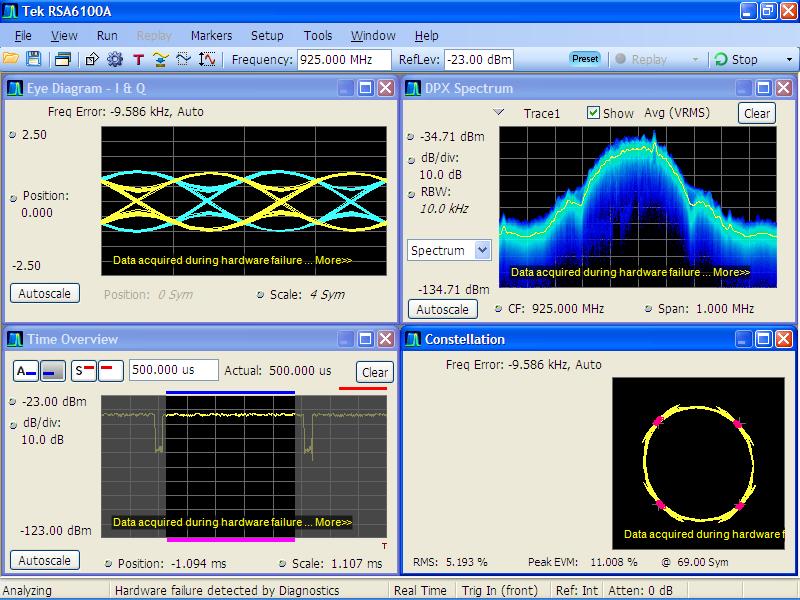
Ok. With this FPGA image and the following initialization sequence, I get signal. OpenBTS output is pretty clean as shown in the attachment. Note that I halved the GSM symbol rate because for some strange reason, I was not able to run OpenBTS with two samples-per-symbol, though I was able to send a tone with tx_waveforms at the same sample rate.
So this is 'slow' GSM at 135 kHz, but the point was to get sampling above Nyquist to capture any distortion from the device and not OpenBTS itself. There is noticeable IQ imbalance, but I guess that is just uncorrected. Also, please ignore the failure messages on our test equipment (we have a converter spec issue).
Is there a similar sequence to enable Rx?
Thomas
Looks like it is not correctly initialized. Try using the same initialization sequence as I do:
./umtrx_lms.py --lms 1 --lms-init ./umtrx_lms.py --lms 1 --lms-tx-enable 1 #./umtrx_lms.py --lms 1 --lms-rx-enable 1 # Select 0.75MHz LPF ./umtrx_lms.py --lms 1 --reg 0x34 --data 0x3e ./umtrx_lms.py --lms 1 --pll-ref-clock 26e6 --lpf-bandwidth-code 0x0f --lms-auto-calibration # Manual DC calibration ./umtrx_lms.py --lms 1 --reg 0x42 --data 0x71 ./umtrx_lms.py --lms 1 --reg 0x43 --data 0x89 ../build/utils/uhd_cal_tx_dc_offset --compl_i 0.001 --compl_q 0 # Tuning ./umtrx_lms.py --lms 1 --lms-tx-pll-tune 925e6 ./umtrx_lms.py --lms 1 --lms-pa-on 2
On Mon, Jun 18, 2012 at 4:17 AM, Thomas Tsou thomastsou@gmail.com wrote:
There is noticeable IQ imbalance, but I guess that is just uncorrected.
Yes, after the automatic DC offset calibration with --lms-auto-calibration, you should manually calibrate Tx DC offset and Tx IQ imbalance as described at the guide I attached (sections 4.8 and 4.9)/ Also look at the Starter manual section 6 for a more step by step, but high-level guide.
I and Q channel DC calibration could be done with this commands (this is internal to LMS): ./umtrx_lms.py --lms 1 --reg 0x42 --data 0x<val> ./umtrx_lms.py --lms 1 --reg 0x43 --data 0x<val>
And you could control I/Q balance with this command (done in FPGA at 13MSPS): ../build/utils/uhd_cal_tx_dc_offset --compl_i <val> --compl_q <val>
Is there a similar sequence to enable Rx?
Nothing really tested yet. At least you should do this steps: ./umtrx_lms.py --lms 1 --lms-rx-enable 1 ./umtrx_lms.py --lms 1 --lms-rx-pll-tune 925e6 ./umtrx_lms.py --lms 1 --pll-ref-clock 26e6 --lpf-bandwidth-code 0x0f --lms-auto-calibration
Then you need to select Rx input with register 0x75. Should be something like this: ./umtrx_lms.py --lms 1 --reg 0x75 --data 0xF0
There are a lot of other settings for Rx fontend in LMS which I don't understand, but I guess defaults should be fine for the start. Then we could tune them with Andrey's help.
If signal is too low you may need to tune Rx VGA2 gain with the register 0x65 (refer to the programming guide for the register values encoding).
To simplify further use we should add these controls to the LMS control script.
On Mon, Jun 18, 2012 at 1:31 AM, Alexander Chemeris alexander.chemeris@gmail.com wrote:
Nothing really tested yet. At least you should do this steps: ./umtrx_lms.py --lms 1 --lms-rx-enable 1 ./umtrx_lms.py --lms 1 --lms-rx-pll-tune 925e6 ./umtrx_lms.py --lms 1 --pll-ref-clock 26e6 --lpf-bandwidth-code 0x0f --lms-auto-calibration
Then you need to select Rx input with register 0x75. Should be something like this: ./umtrx_lms.py --lms 1 --reg 0x75 --data 0xF0
There are a lot of other settings for Rx fontend in LMS which I don't understand, but I guess defaults should be fine for the start. Then we could tune them with Andrey's help.
If signal is too low you may need to tune Rx VGA2 gain with the register 0x65 (refer to the programming guide for the register values encoding).
Connected a call - all seven actually. It's quite stable once setup.
'fairwaves/umtrx' branch with u2plus_umtrx-20120424.bit and following patch. I and Q were swapped.
Thomas
On Wed, Jun 20, 2012 at 5:33 AM, Thomas Tsou thomastsou@gmail.com wrote:
On Mon, Jun 18, 2012 at 1:31 AM, Alexander Chemeris alexander.chemeris@gmail.com wrote:
Nothing really tested yet. At least you should do this steps: ./umtrx_lms.py --lms 1 --lms-rx-enable 1 ./umtrx_lms.py --lms 1 --lms-rx-pll-tune 925e6 ./umtrx_lms.py --lms 1 --pll-ref-clock 26e6 --lpf-bandwidth-code 0x0f --lms-auto-calibration
Then you need to select Rx input with register 0x75. Should be something like this: ./umtrx_lms.py --lms 1 --reg 0x75 --data 0xF0
There are a lot of other settings for Rx fontend in LMS which I don't understand, but I guess defaults should be fine for the start. Then we could tune them with Andrey's help.
If signal is too low you may need to tune Rx VGA2 gain with the register 0x65 (refer to the programming guide for the register values encoding).
Connected a call - all seven actually. It's quite stable once setup.
Good job!
How did you setup Rx on LMS? And anything else to know before testing?
'fairwaves/umtrx' branch with u2plus_umtrx-20120424.bit and following patch.
Now it's time to make this a configure option. :)
I and Q were swapped.
So I/Q order is different at Rx and Tx?We could fix this in FPGA.
With the multi-ARFCN support, do you think it will be hard to add support for the second channel in UmTRX to OpenBTS to get 15 calls? Second channel is not fully supported by UmTRX FPGA firmware yet, but we should do this soon.
On Wed, Jun 20, 2012 at 8:11 AM, Alexander Chemeris alexander.chemeris@gmail.com wrote:
On Wed, Jun 20, 2012 at 5:33 AM, Thomas Tsou thomastsou@gmail.com wrote:
On Mon, Jun 18, 2012 at 1:31 AM, Alexander Chemeris alexander.chemeris@gmail.com wrote:
Nothing really tested yet. At least you should do this steps: ./umtrx_lms.py --lms 1 --lms-rx-enable 1 ./umtrx_lms.py --lms 1 --lms-rx-pll-tune 925e6 ./umtrx_lms.py --lms 1 --pll-ref-clock 26e6 --lpf-bandwidth-code 0x0f --lms-auto-calibration
Then you need to select Rx input with register 0x75. Should be something like this: ./umtrx_lms.py --lms 1 --reg 0x75 --data 0xF0
There are a lot of other settings for Rx fontend in LMS which I don't understand, but I guess defaults should be fine for the start. Then we could tune them with Andrey's help.
If signal is too low you may need to tune Rx VGA2 gain with the register 0x65 (refer to the programming guide for the register values encoding).
Connected a call - all seven actually. It's quite stable once setup.
Good job!
How did you setup Rx on LMS? And anything else to know before testing?
'fairwaves/umtrx' branch with u2plus_umtrx-20120424.bit and following patch.
Now it's time to make this a configure option. :)
I and Q were swapped.
So I/Q order is different at Rx and Tx?We could fix this in FPGA.
With the multi-ARFCN support, do you think it will be hard to add support for the second channel in UmTRX to OpenBTS to get 15 calls? Second channel is not fully supported by UmTRX FPGA firmware yet, but we should do this soon.
Actually interesting would be to test UmTRX with your multi-ARFCN code to see how many channels we could fit into.
I wonder how do you select/measure rx_smpl_offset. My guess is that you write both Tx and Rx I/Q streams to files, plot them and try to align frame starts. Is that how do you do this?
PS Could you record a short video of making 7 calls through UmTRX? We should make some noise or people forget what we're doing.
On Wed, Jun 20, 2012 at 12:33 AM, Alexander Chemeris alexander.chemeris@gmail.com wrote:
Actually interesting would be to test UmTRX with your multi-ARFCN code to see how many channels we could fit into.
I tried this briefly but the transmit output was cutoff by LPF. I'll try it again with different LMS settings at the end of the week.
I wonder how do you select/measure rx_smpl_offset. My guess is that you write both Tx and Rx I/Q streams to files, plot them and try to align frame starts. Is that how do you do this?
I mainly use two approaches. In the first method, feed the baseband output to a scope (optionally set the transceiver filler table with easy to recognizable values). Set one output of a dual function generator to trigger the scope at the frame rate. Use the second function generator output (with low duty cycle) to select individual timeslots and also trigger an RF signal generator that feeds back to the device. The offset can then be detected using the receiver energy detector.
The second much quicker (and generally more effective) approach is to simply measure with a handset. Disable upper layer RACH handling and average the RACH burst TOA values over a few attempts and different handsets. This delay value is the effective combined group delay (relative to the sample counter) of host and device filters, RF components, feed line, etc.
I rarely use first approach, but sometimes absolutely nothing works and the test equipment needs to be used to get a better picture.
PS Could you record a short video of making 7 calls through UmTRX? We should make some noise or people forget what we're doing.
I could record a (low quality) video with my phone. That is the only video recorder I have available right now. I can take pretty good pictures though.
Thomas
On Wed, Jun 20, 2012 at 12:11 AM, Alexander Chemeris alexander.chemeris@gmail.com wrote:
On Wed, Jun 20, 2012 at 5:33 AM, Thomas Tsou thomastsou@gmail.com wrote:
On Mon, Jun 18, 2012 at 1:31 AM, Alexander Chemeris alexander.chemeris@gmail.com wrote:
Nothing really tested yet. At least you should do this steps: ./umtrx_lms.py --lms 1 --lms-rx-enable 1 ./umtrx_lms.py --lms 1 --lms-rx-pll-tune 925e6 ./umtrx_lms.py --lms 1 --pll-ref-clock 26e6 --lpf-bandwidth-code 0x0f --lms-auto-calibration
Then you need to select Rx input with register 0x75. Should be something like this: ./umtrx_lms.py --lms 1 --reg 0x75 --data 0xF0
There are a lot of other settings for Rx fontend in LMS which I don't understand, but I guess defaults should be fine for the start. Then we could tune them with Andrey's help.
If signal is too low you may need to tune Rx VGA2 gain with the register 0x65 (refer to the programming guide for the register values encoding).
Connected a call - all seven actually. It's quite stable once setup.
Good job!
How did you setup Rx on LMS? And anything else to know before testing?
I used some combination of the above Rx settings and the previous Tx sequence. I don't recall the exact order, but I didn't use any commands or arguments that haven't been mentioned. I didn't change the VGA2 setting and for much of the testing had a 3dB attenuator on the LNA input (probably didn't matter).
Remember to set the ARFCN to match the tuning frequencies. I did not and spent some time trying to figure out why only RACH bursts were decoded.
'fairwaves/umtrx' branch with u2plus_umtrx-20120424.bit and following patch.
Now it's time to make this a configure option. :)
UmTRX could be detected at runtime. There are already device checks for USRP1 and B100.
I and Q were swapped.
So I/Q order is different at Rx and Tx?We could fix this in FPGA.
With the multi-ARFCN support, do you think it will be hard to add support for the second channel in UmTRX to OpenBTS to get 15 calls? Second channel is not fully supported by UmTRX FPGA firmware yet, but we should do this soon.
The OpenBTS side should be straightforward. The multicarrier implementation accepts independent transceiver inputs with the channelization acting as multiplexer. With separate physical channels, we just remove the channelization and pass transceiver connections straight through to the device interface.
I added the second Tx channel in UHD some time ago, but never created a test case.
Thomas

Hi,
I've fixed reading data order from the receive ADCs. You can found it in fairwaves/umtrx branch (commit e2e5dc62317a714944e9d54b56240fca5336e2ca).
2012/6/20 Thomas Tsou thomastsou@gmail.com
'fairwaves/umtrx' branch with u2plus_umtrx-20120424.bit and following patch. I and Q were swapped.
Regards, Andrew Karpenkov
Andrew,
Thanks for the fix. Now we should merge Sylvain's GPSDO changes into the master branch and make a build with both changes to upload to the web-site. Could you do this and send me both .bit and .bin files?
PS Do not forget to build fresh bootloader, it's also changed by GPSDO update.
On Wed, Jun 20, 2012 at 6:18 PM, Andrew Karpenkov plddesigner@gmail.com wrote:
Hi,
I've fixed reading data order from the receive ADCs. You can found it in fairwaves/umtrx branch (commit e2e5dc62317a714944e9d54b56240fca5336e2ca).
2012/6/20 Thomas Tsou thomastsou@gmail.com
'fairwaves/umtrx' branch with u2plus_umtrx-20120424.bit and following patch. I and Q were swapped.
Regards, Andrew Karpenkov
I've done it. tx_waveforms work fine. Both .bit and .bin files attached. Please, check other function of UmTRX board with this flash image. Repository at github was also updated.
Regards, Andrew Karpenkov
2012/6/20 Alexander Chemeris alexander.chemeris@gmail.com
Andrew,
Thanks for the fix. Now we should merge Sylvain's GPSDO changes into the master branch and make a build with both changes to upload to the web-site. Could you do this and send me both .bit and .bin files?
PS Do not forget to build fresh bootloader, it's also changed by GPSDO update.
On Wed, Jun 20, 2012 at 6:18 PM, Andrew Karpenkov plddesigner@gmail.com wrote:
Hi,
I've fixed reading data order from the receive ADCs. You can found it in fairwaves/umtrx branch (commit e2e5dc62317a714944e9d54b56240fca5336e2ca).
2012/6/20 Thomas Tsou thomastsou@gmail.com
'fairwaves/umtrx' branch with u2plus_umtrx-20120424.bit and following patch. I and Q were swapped.
Regards, Andrew Karpenkov
-- Regards, Alexander Chemeris. CEO, Fairwaves LLC / ООО УмРадио http://fairwaves.ru
On Mon, Jun 11, 2012 at 7:12 AM, Alexander Chemeris alexander.chemeris@gmail.com wrote:
On Mon, Jun 11, 2012 at 4:08 AM, Thomas Tsou thomastsou@gmail.com wrote:
If the load drops down and the signal transmits, I wouldn't worry about it for now. The likely condition is that there is a offset between the initial arriving timestamp and the expected timestamp. Because the receive timestamps drive the transceiver, the receiver may run at 100% until the timestamp and expected value align. If OpenBTS transmits consistently, then the system is in sync.
Aah! Yes, we have some issue with setting the timestamp with UmTRX. E.g. I had to modify UHD examples which set timestamp to 0 on startup and rely on this later on. With my change they read the actual value of the timestamp and start from that. Could we do the same for OpenBTS?
I'm running into this issue now, which was the reason I wasn't always seeing transmit output. Workaround patch is attached along with the corrected 'normal' rate GSM signal.
Thomas
-
 Alexander Chemeris
 -
 Andrew Karpenkov
 -
 Sylvain Munaut
 -
 Thomas Tsou