HI!
I want grab audio from my sdr-device and convert it to h264.
I use rtl_fm, check any options, but I can't listen any good sound :(
For example: rtl_fm -f 10000000 -s 44100 - | mplayer - -quiet
-rawaudio rate=8000:bitrate=44100 -demuxer rawaudio
Can you help me?
May be anybody know any software for me?
Thank you!
--
live free or die;
-----BEGIN PGP SIGNED MESSAGE-----
Hash: SHA1
Hello everybody,
since we found out that the Atmel SAM3U SSC interface is only capable
of transporting 500ksps worth of I/Q data, we heard a lot of
complaining because of the too narrow bandwith. Especially compared to
the rtl-sdr with about 2msps, our 500ksps was bit contrained. The
fact, that the OsmoSDR is much more sensitive to very small signals
and brings a 14bit ADC instead of 8bits did not really compensate for
the bandwidth loss.
Also the mismatch between E4000 output resistance and ADC input
brought some unwanted spectral effects.
Instead of just releasing stuff, we decided to fix both issues: I now
have a prototype with simple stack-on-board, that adds two op-amps to
decouple the E4000 from the ADC and lower the impedance and also this
board connecteds the available FPGA pins to the MCI (SD-Card)
interface of the Atmel SAM3U.
For this to get working, we had to rewrite major parts of the ARM
firmware and the FPGA VHDL code. Today this work is completed and I
can report success: The OsmoSDR now delivers up to 4msps at 14bits.
Also the strange peaks around Niquist/zero frequency are gone.
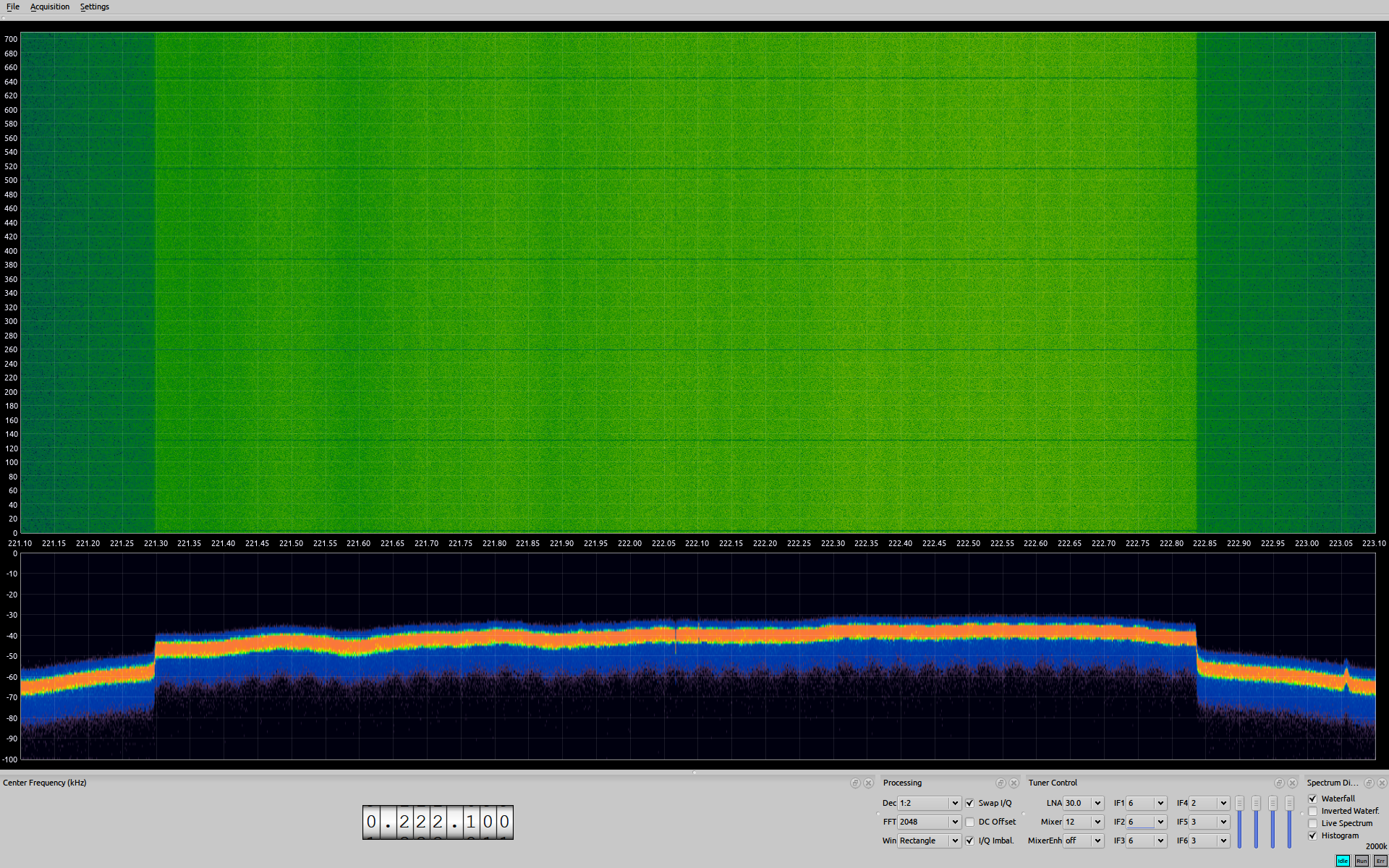
Find a screenshot of SDRangelove recording a DAB signal at 2msps
(SDRangelove needs some more love until it can cope with 4msps in
realtime - but we have verified that 4msps works without dropped
samples using the builtin FPGA test mode).
http://www.cdaniel.de/download/osmosdr-dab-2mhz.png
We will now integrate the changes into the OsmoSDR mainboard and
reroute the now free SSC pins to the pin headers instead of the MCI
interface. Also we will add the opamps.
For the already produced OsmoSDR boards, we will have more of the
prototype stack-on-top-boards.
We will keep you in the loop!
Best regards,
Christian
PS: Regarding the DAB screenshot:
- - The horizontal lines are correct - DAB uses a so called "pilot
symbol", which only has energy on a few carriers. That's why it looks
like a pause in the signal.
- - The vertical line is also correct - DAB does not use the middle
carrier to avoid I/Q offset problems on the transmitter side.
- --
- ---------------------------------------------------
| maintech # Dipl. Inf (FH) Christian Daniel |
| GmbH ### Otto-Hahn-Str. 15 · D-97204 Höchberg |
- ---------------------------------------------------
| AG Würzburg, HRB 8790 Tax-ID DE242279645 |
- ---------------------------------------------------
| http://www.maintech.de cd(a)maintech.de |
- ---------------------------------------------------
-----BEGIN PGP SIGNATURE-----
Version: GnuPG v1.4.11 (GNU/Linux)
Comment: Using GnuPG with Mozilla - http://www.enigmail.net/
iQEcBAEBAgAGBQJQfuMIAAoJEHkgzUIsAWriHA0IAI2Agg0vnjLFa5dDpxu9AAkq
6crr1Q/XAgrlmN8TY86yoYTMjJc7IZmjsAAGpidczZtSbwbmLFuTdQEo12dOvaZZ
GvkvNttoDE2zsnbU50MzWDK5BUcbfOJoQahX26P+8hbiaIsFKT8Gl8Ao9c2vz79u
e04Cl2SodmDDKnV84VL9i39+KZdkGcsbCWnFizqGzTbWyDkoSVviZORp20a3lCEZ
g8Af73jwDgVAU4lfrK9gO10G5jibHkQeULNIXFH8NbDiUPSF2557fGsu/9yC1UUC
msT0g41x8twb5nesT4ZtWDfQ3tUBgvLHn/ebv9xBxCX1Wg1W2FAFlcajbXx4zRQ=
=Taca
-----END PGP SIGNATURE-----
Hi! I just released a major update to the LTE code. There's a new program
called LTE-Tracker that camps on a certain frequency and tracks, any LTE
cells that it finds.
Interesting features (all are in realtime):
- You can see cells popping in and dropping off as the receiver is moved
around the coverage area of the different cells.
- You can see the actual transfer function of the wireless channel
plotted on the screen.
I've also made a small change to CellSearch so that now, it also displays
the number of antennas (ports) on the basestation.
Please let me know of any comments or suggestions!
http://www.evrytania.com/lte-tools/lte-tracker
James
--
*Integrity is a binary state - either you have it or you don’t.* - John
Doerr
I have gnuradio running with the R820D DVB. Latest GQRX has the nice rf
gain inside which REALLY helps. Has this been merged over to gr-osmosdr ? I
recompiled probably just a few days, both from source.
I'm trying to figure out how to set gain from within gnuradio (is there a
argument I can pass the device in the source block?).
I've been successfully decoding AFSK1200 APRS using gqrx and am trying to
figure out how to set up an ultracheap iGate for APRS, maybe with gnuradio
in the mix.
Also using the OSMOSDR block I still see an LO like spike right in the
middle.
Here's my output starting GQRX. Interesting it's saying gr-osmosdr
supported device types...
ron@tripel:~$ startGqrx.sh
ron@tripel:~$ gr-osmosdr supported device types: file fcd rtl rtl_tcp uhd
>>> gr_fir_ccf: using 3DNow!
>>> gr_fir_ccc: using 3DNow!Ext
>>> gr_fir_fff: using 3DNow!
gr-osmosdr supported device types: file fcd rtl rtl_tcp uhd
Using device #0: Generic RTL2832U (e.g. hama nano)
Found Rafael Micro R820T tuner
TIA!
-Ron / KB1UMH
Hi.
I have tried (in a bash shell):
rtl_fm -f 96.3e6 -s 48000 - | aplay -r raw -f dat -c 1
That was proposed somewhere as an example to listen to an FM station. But
everything terminates with:
aplay: main:576: bad speed value 0
Found 1 device(s):
0: Realtek, RTL2838UHIDIR, SN: 00000013
Using device 0: ezcap USB 2.0 DVB-T/DAB/FM dongle
Found Rafael Micro R820T tuner
Oversampling input by: 21x.
Oversampling output by: 1x.
Buffer size: 8.13ms
Tuned to 96552000 Hz.
Sampling at 1008000 Hz.
Output at 48000 Hz.
Exact sample rate is: 1008000.009613 Hz
Tuner gain set to automatic.
Signal caught, exiting!
User cancel, exiting...
I run Fedora 16 on a 64-bit AMD machine. aplay version is 1.0.26
If I break the command apart and generates a intermediate file it works but
using a pipe does not.
So is there some other shell that I where this might work or is there some
better why to do this?
Regards
Olof
> Vitaliy Kulchevych coolchevy at gmail.com
> Wed Nov 14 19:01:02 CET 2012
>
> I want grab audio from my sdr-device and convert it to h264.
>
> I use rtl_fm, check any options, but I can't listen any good sound :(
>
> For example: rtl_fm -f 10000000 -s 44100 - | mplayer - -quiet
> -rawaudio rate=8000:bitrate=44100 -demuxer rawaudio
My apologies for breaking threading on this message - just signed up
to the ML today.
I can't help you without a lot more information. Is this a narrow band
or a wide band FM signal? Do you want to save the audio to a file or
a network stream? What operating system are you using? Why are you
trying to compress an audio stream with a video codec?
-Kyle
http://kmkeen.com
Hi!
I was trying to compile the osmocom sdr project and also trying to report a
compilation error.
I will like to have an account to contribute.
this was the error I got:
In file included from
/home/llazzaro/tmp/gr-osmosdr/lib/osmosdr_source_c_impl.h:23:0,
from
/home/llazzaro/tmp/gr-osmosdr/lib/osmosdr_source_c_impl.cc:30:
/home/llazzaro/tmp/gr-osmosdr/include/osmosdr/osmosdr_source_c.h: In
constructor ‘osmosdr_source_c::osmosdr_source_c()’:
/home/llazzaro/tmp/gr-osmosdr/include/osmosdr/osmosdr_source_c.h:57:19:
error: no matching function for call to ‘gr_hier_block2::gr_hier_block2()’
/home/llazzaro/tmp/gr-osmosdr/include/osmosdr/osmosdr_source_c.h:57:19:
note: candidates are:
/usr/include/gnuradio/gr_hier_block2.h:57:3: note:
gr_hier_block2::gr_hier_block2(const string&, gr_io_signature_sptr,
gr_io_signature_sptr)
/usr/include/gnuradio/gr_hier_block2.h:57:3: note: candidate expects 3
arguments, 0 provided
/usr/include/gnuradio/gr_hier_block2.h:43:7: note:
gr_hier_block2::gr_hier_block2(const gr_hier_block2&)
/usr/include/gnuradio/gr_hier_block2.h:43:7: note: candidate expects 1
argument, 0 provided
/home/llazzaro/tmp/gr-osmosdr/lib/osmosdr_source_c_impl.cc: In constructor
‘osmosdr_source_c_impl::osmosdr_source_c_impl(const string&)’:
/home/llazzaro/tmp/gr-osmosdr/lib/osmosdr_source_c_impl.cc:83:35: note:
synthesized method ‘osmosdr_source_c::osmosdr_source_c()’ first required
here
make[2]: ***
[lib/CMakeFiles/gnuradio-osmosdr.dir/osmosdr_source_c_impl.cc.o] Error 1
make[1]: *** [lib/CMakeFiles/gnuradio-osmosdr.dir/all] Error 2
make: *** [all] Error 2
--
http://www.lazzaroleonardo.com.ar/
twitter @llazzaro
Hi all,
I've been looking at the E4000 tuner code and I have a couple of questions
that aren't answered in the datasheet. I'm hoping someone here might have
some insight.
In the Elonics-supplied code[1] when setting the frequency (around line 1339),
they always write a 1 into register 0x07 (Synth1), which is the "PLL locked"
register. Does this affect anything? The datasheet says it's read only and
librtlsdr only ever reads this value, it never writes to it.
Then, beginning at 82.9MHz and continuing at every multiple of 28.8MHz above
this, the first 7MHz is tuned differently, but the rest of the 21.8MHz in that
"channel" is set normally. This stops between 233.9MHz and 485.6MHz, then
resumes again at 8MHz increments instead of 7MHz up until 868MHz.
When tuned differently, register 0x05 (Input clock) gets set to 3, which isn't
listed in the datasheet (and also says 'do not write to this register').
Mostly (but not always) when this happens (i.e. first 7-8MHz of the channel),
register 0x07 bits 3-4 are also set to various arbitrary values. The
datasheet says 0 means "16-32MHz input clock freq range" but this code writes
1 and 2 into this field as well. It seems to write approximately these values:
1 up to 89.9MHz
0 up to 118.7MHz
1 up to 205.1MHz
2 up to 233.9MHz
0 up to 551.2MHz
1 up to 752.8MHz
2 up to 868MHz
0 after 868MHz
After the first 7-8MHz the rest of the 28.8MHz channel has the default 0 value
set.
Does anyone know what these values control?
As a side note, register 0x08 (Synth2) appears to do something even though
it's listed as reserved. By setting particular bits I can get the rtl_test
program to not lock on to any frequency, but oddly enough rtl_fm still works
fine. I'm not sure what to make of this yet. I don't suppose this register
is documented anywhere else? I'm just wondering whether the datasheets
supplied by Elonics are different to the one that is now public.
Thanks,
Adam.
[1]: One of many copies is at
https://github.com/mbarbon/rtl2832/blob/master/tuners/tuner_e4000.c
Hello
I've tried to remove the L-band gap on my E4000 tuner by changing the
divisors. Please see the patch below. I don't have a signal source to test
today, so i'm not sure if it works, but the pll locks. I will try to test
tomorrow.
Without my hack: E4K L-band gap: 1093 to 1233 MHz
With my hack:
sq5bpf@dellix:~/gnuradio/rtl-sdr/src$ ./rtl_test -t
Found 1 device(s):
0: ezcap USB 2.0 DVB-T/DAB/FM dongle
Using device 0: ezcap USB 2.0 DVB-T/DAB/FM dongle
Found Elonics E4000 tuner
Supported gain values (14): -1.0 1.5 4.0 6.5 9.0 11.5 14.0 16.5 19.0 21.5
24.0 29.0 34.0 42.0
Benchmarking E4000 PLL...
[E4K] PLL not locked for 51000000 Hz!
[E4K] PLL not locked for 2186000000 Hz!
E4K range: 52 to 2185 MHz
E4K L-band gap: 0 to 0 MHz
Regards
Jacek / SQ5BPF
--- tuner_e4k.c.orig 2012-11-08 22:08:07.000000000 +0100
+++ tuner_e4k.c 2012-11-08 23:01:05.000000000 +0100
@@ -35,6 +35,7 @@
/* If this is defined, the limits are somewhat relaxed compared to what the
* vendor claims is possible */
#define OUT_OF_SPEC
+#define HACKED_DIVISORS
#define MHZ(x) ((x)*1000*1000)
#define KHZ(x) ((x)*1000)
@@ -357,7 +358,14 @@
{KHZ(350000), (1 << 3) | 1, 8},
{KHZ(432000), (0 << 3) | 3, 8},
{KHZ(667000), (0 << 3) | 2, 6},
- {KHZ(1200000), (0 << 3) | 1, 4}
+#ifdef HACKED_DIVISORS
+/* the original settings seem to be ripped from some Elonics driver,
+ * however changing them a bit removes the L-band gap
+ * change this to a bit more then the end of your L-band gap --sq5bpf */
+ {KHZ(1270000), (0 << 3) | 1, 3}
+#else
+ {KHZ(1200000), (0 << 3) | 1, 4}
+#endif
};
static int is_fvco_valid(uint32_t fvco_z)
Hi,
Good news with MSI DIGIVOX Micro HD (1d19:1104) DVB-T tuner. Now the tuner working. Succesfully received analague UHF TV sound channel 80 kilometer distance from transmitter, taxi driver (164 Mhz) and one frequency from 70cm radio amateur band.
The tuner is FCI FC2580 from debug message. I see on http://sdr.osmocom.org/trac/wiki/rtl-sdr great new info for this tuner 146 - 308 MHz and 438 - 924 MHz (gap in between). Not have any wideband generator for check this, but for example with strong local FM radio station 87.5-108MHz tunable, but received only noise. I think the frequency range possibly same. All rtl-sdr DVB-T tuner with fc2850 has a same frequency range? I interesting for not working frequiency, working frequiency or working freq. but poor receiver quality, or any gap. I interesting also for 2 meter radio amateur band, only max. 2 MHz lower. 144-146MHZ only noise received, i not know my antenna bad, or this is not possible.
mngc
This appears to be not tested with autoconf (cmake works). The assignment
to $LIBS changes nothing, which cannot possibly be the intent.
---
cc-ing to original patch author and sign-off
diff --git a/configure.ac b/configure.ac
index 1b94701..c760787 100644
--- a/configure.ac
+++ b/configure.ac
@@ -40,7 +40,7 @@ dnl libmath (for rtl_fm)
AC_CHECK_LIB(m, atan2, [LIBS="$LIBS -lm"])
dnl librealtime (for rtl_test)
-AC_CHECK_LIB(rt, clock_gettime, [LIBS="$LIBS"])
+AC_CHECK_LIB(rt, clock_gettime, [LIBS="$LIBS -lrt"])
# The following test is taken from WebKit's webkit.m4
saved_CFLAGS="$CFLAGS"
I'm running Ubuntu 12.04 and after installing all the latest security and
recommended updates, I'm having problems with the rtlsdr library relating
to rtlsdr_cancel_async. For example:
rtl_sdr -f 739000000 -n 1000000 cap.dat
The above will successfully capture exactly 1M samples into cap.dat, but it
will not exit after the capture is finished. I have to break out with
ctrl-c.
Anybody having similar problems? Hoping I don't have to re-install
Ubuntu... :(
James
--
*Integrity is a binary state - **either you have it or you don’t.* - John
Doerr
Just fyi, here's how I did the 4msps wiring hack :
http://i.imgur.com/TODkU.png
Basically use resistors (I used 270R which is a bit high ,between 20 and
10R would bwe better) on the back side on the PCB.
I initially started with wire jumpers on the pins, then moved to resisors
on the top but that created a huge loop area with the ground return (there
is no gnd on those connection) which was heavily radiating.
Mounting on the back like that dropped it significantely for me (especially
on baseband), but you still clearly see it.
I think the FPGA drive strength on the data pins is still way too high and
should be reduced.
Maybe using spread spectrum on the MCI would be another idea ?
Cheers,
Sylvain


